Multi-axis device
View Connectio
n
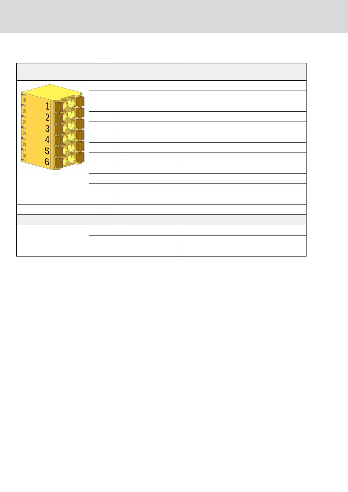
Signal name Function
1 STO_DynOut_CH1 Channel 1 dynamization output
2 - n. c.
3 STO_Ax1_CH1 Input for selection of axis 1, channel 1
4 STO_Ax1_CH1 Input for selection of axis 1, channel 1
5 STO_Ax2_CH1 Input for selection of axis 2, channel 1
6 STO_Ax2_CH1 Input for selection of axis 2, channel 1
7 STO_DynOut_CH2 Channel 2 dynamization output
8 - n. c.
9 STO_Ax1_CH2 Input for selection of axis 1, channel 2
10 STO_Ax1_CH2 Input for selection of axis 1, channel 2
11 STO_Ax2_CH2 Input for selection of axis 2, channel 2
12 STO_Ax2_CH2 Input for selection of axis 2, channel 2
Spring terminal (connector) Unit min. max.
Connection cable
Stranded wire
mm
2
0.2 1.5
AWG 24 16
Stripped length mm - 10
Tab. 10-20: XG41, safety technology Safe Torque Off
88/123
Mounting, dismounting and electrical installation
IndraDrive X Drive Controllers Power Sections XCS1, XMD1,
XMQ1
Bosch Rexroth AG R911392532_Edition 01
 Loading...