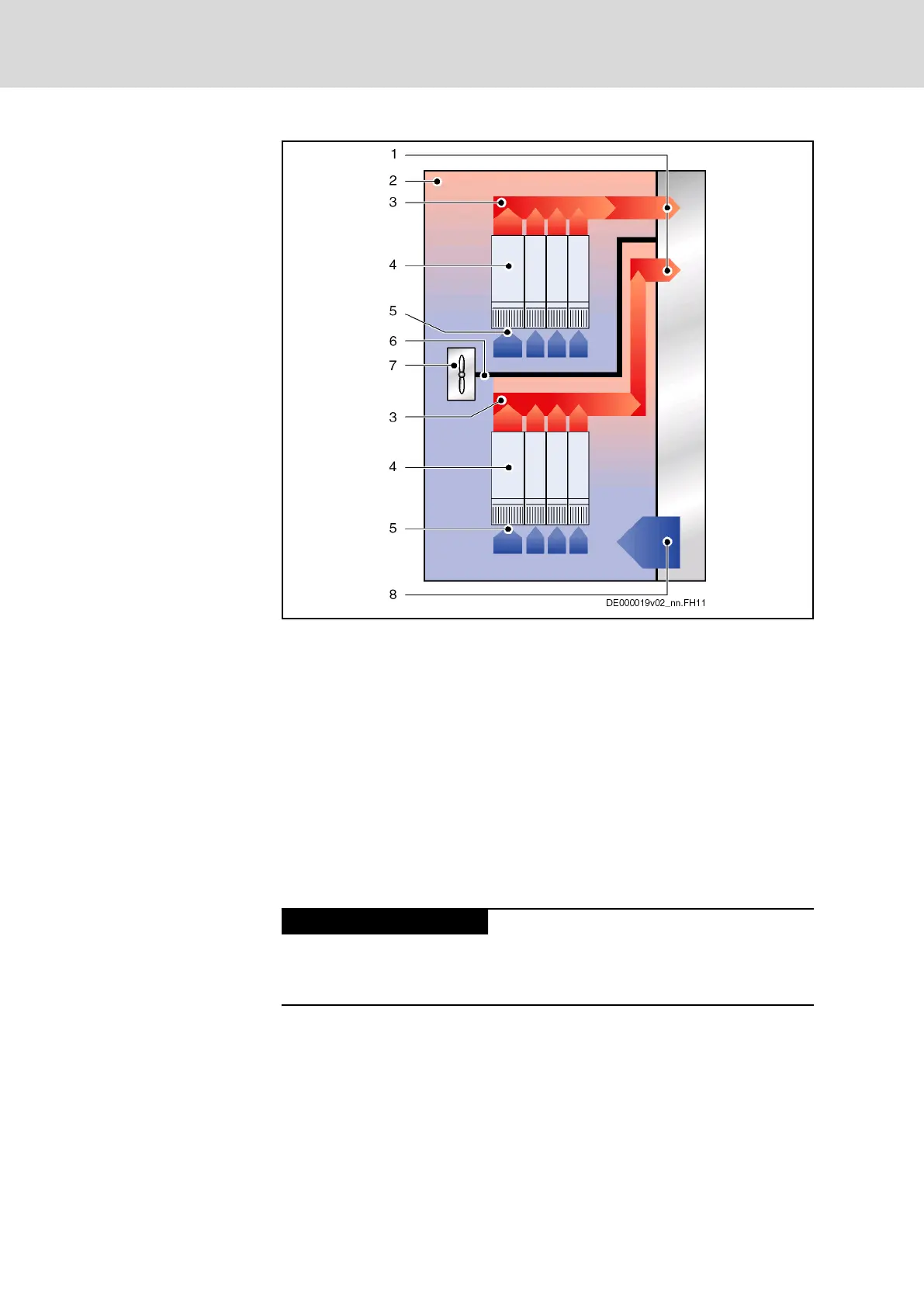
1 Discharge of heated air to cooling unit
2 Interior of control cabinet
3 Conveying direction of heated air in area where air flows off
4 Device in control cabinet
5 Air intake at device
6 Air guide in control cabinet (for liquid cooling, this is also the
drip protection for the devices beneath)
7 Fan in control cabinet
8 Supply of cooled air from cooling unit
Fig. 10-2: Examplary arrangement of double-line design
Arranging the cooling units
Unless the nominal data are reduced, the drive controller may only be
operated up to a specified maximum ambient temperature. A cooling unit
might therefore be required.
Possible damage to the drive controller!
Operational safety of the machine
endangered!
Observe the instructions below.
Avoiding dripping or spraying wa‐
ter
Due to their operating principle, condensation water is formed when cooling
units are used.
For this reason, observe the following aspects:
● Always position cooling units in such a way that condensation water
cannot drip onto the devices in the control cabinet.
48/123
Mounting, dismounting and electrical installation
IndraDrive X Drive Controllers Power Sections XCS1, XMD1,
XMQ1
Bosch Rexroth AG R911392532_Edition 01