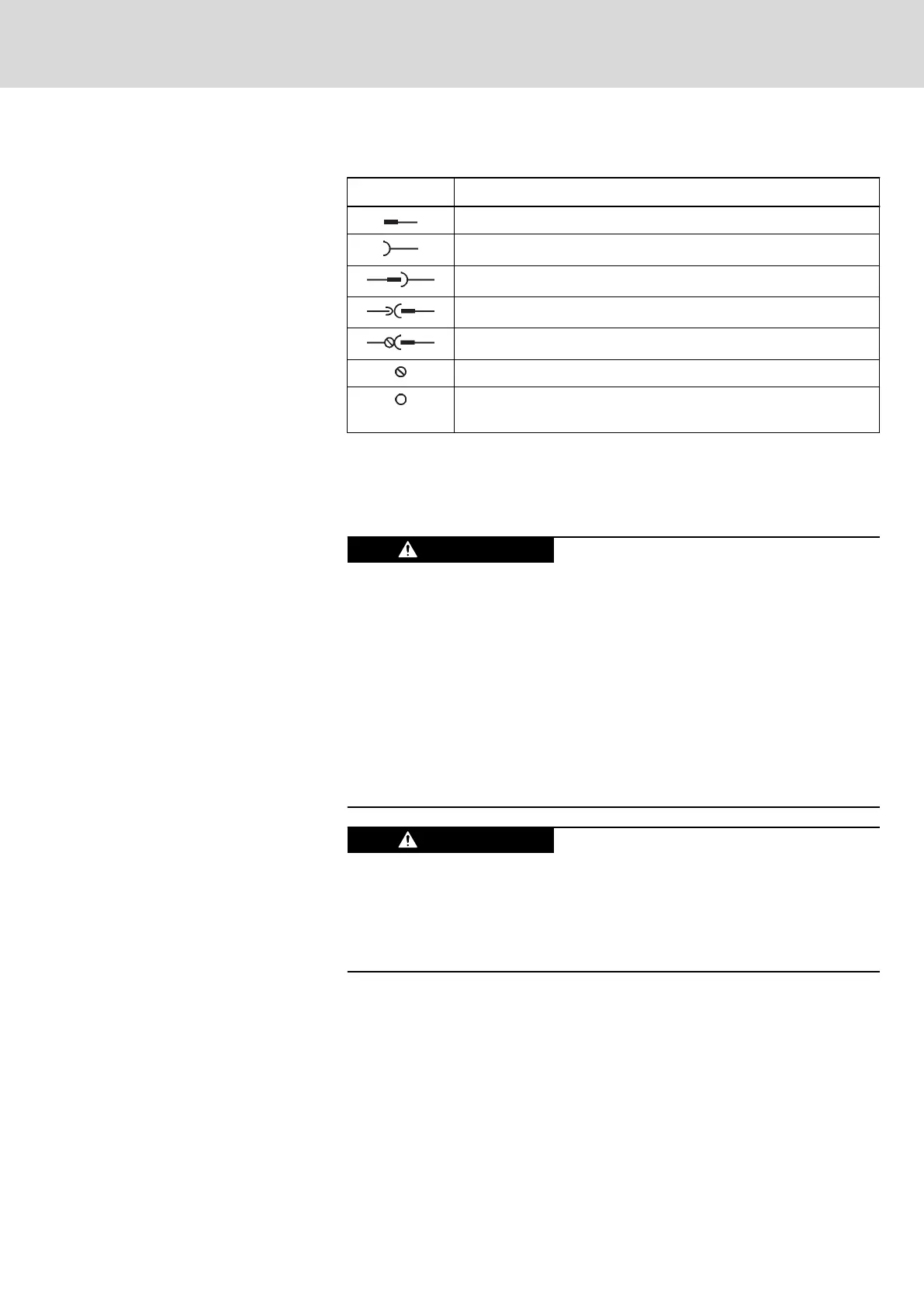
Symbols (connection diagram)
Symbol Description
Pin
Female connector
Male connector (pin at connector; female [device])
Spring terminal (female [connector], pin at device)
Screw terminal (female [connector], pin at device)
Screw connection at device
Electrical connection at device housing (e.g., for cable shield
connection)
Tab. 10-3: Symbols (connection diagram)
10.5.5 On-board connection points
Equipment grounding conductor
High housing voltage and high leakage
current! Danger to life, risk of injury by
electric shock!
● Before switching on and before commissioning, ground or connect the
components of the electric drive and control system to the equipment
grounding conductor at the grounding points.
● Connect the equipment grounding conductor of the components of the
electric drive and control system permanently to the main power supply
at all times. The leakage current is greater than 3.5 mA.
● Establish an equipment grounding connection with a copper wire of a
cross section of at least 10 mm
2
(8 AWG) or additionally run a second
equipment grounding conductor of the same cross section as the
original equipment grounding conductor.
Lethal electric shock by live parts with more
than 50 V!
Only operate the device
● with the connectors plugged on (even if no lines have been connected
to the connectors) and
● with the equipment grounding conductor connected!
IndraDrive X Drive Controllers Power Sections XCS1, XMD1,
XMQ1
69/123
Mounting, dismounting and electrical installation
R911392532_Edition 01 Bosch Rexroth AG