10 Mounting, dismounting and electrical installation
10.1 Information on mounting
10.1.1 Control cabinet
Information on control cabinet mounting
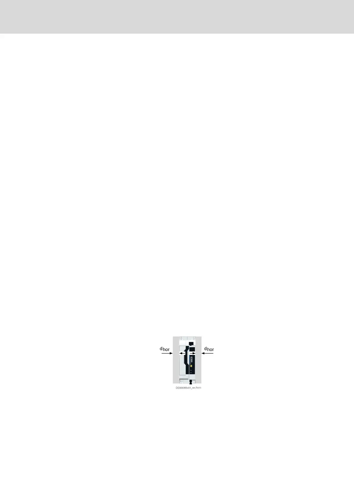
● Observe the minimum distances to be complied with for mounting (see
technical data or dimensional drawings).
The specified horizontal minimum distance (d
hor
) refers to the distance
to neighboring IndraDrive X devices or equipment installed in the control
cabinet (such as cable ducts).
The horizontal distance to the control cabinet wall and to other Rexroth
devices (e.g., IndraDrive C, EFC), or to devices of manufacturers other
than Rexroth, has to be ≥ 10 mm.
If IndraDrive X devices are mounted side by side in the control cabinet
without any distances, the DC buses of all devices have to be
interconnected. Otherwise, the devices have to be mounted side by side
with a horizontal distance of ≥ 10 mm.
● The device comes with adhesive labels with safety instructions. These
safety instructions always must remain at the device and be visible.
Immediately replace damaged or illegible safety instructions by flawless
safety instructions.
Required dielectric strength of the connected lines
● Lines at connection points XD01, XD02, XD03, XD04, XD10, XG03,
XZ03:
– Dielectric strength according to basic insulation
– Operational voltage designed for mains voltage and DC bus
voltage (conductor‑conductor: 500 VAC, conductor‑ground:
300 VAC)
● Lines at connection points XG and XF:
– Operational voltage of the corresponding control signal or
communication signal
– Lines run on the left or right side of the device have to be run at a
minmimum distance of d
hor
≥ 10 mm to the device.
If this distance is less than the minimum distance, these lines must
have been designed for the mains voltage and DC bus voltage.
IndraDrive X Drive Controllers Power Sections XCS1, XMD1,
XMQ1
45/123
Mounting, dismounting and electrical installation
R911392532_Edition 01 Bosch Rexroth AG