10.5.4 Connection points
Connection diagram
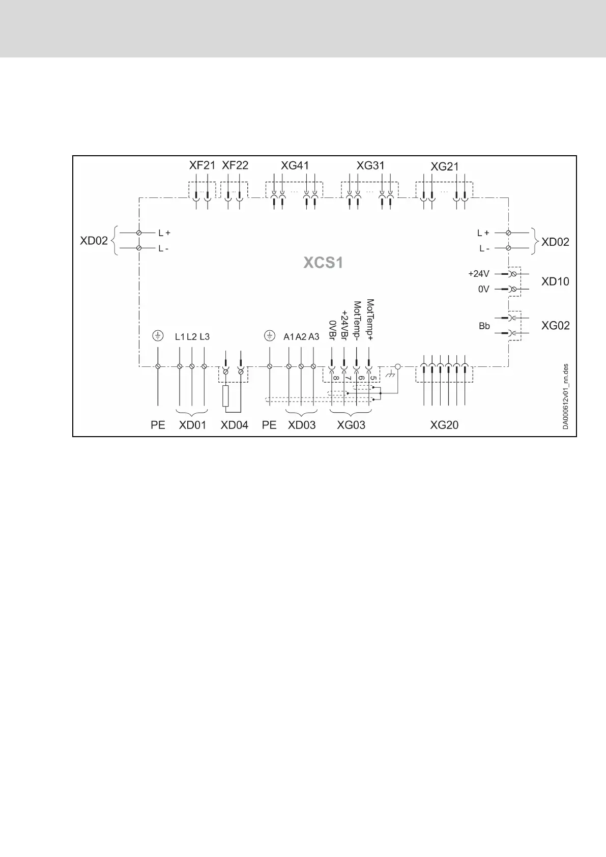
Overall connection diagram XCS1
XD01 Mains
XD02 DC bus
XD03 Motor
XD04 External braking resistor
XD10 Control voltage
XF21, XF22 Communication
XG02 Ready for operation relay contact
XG03 Motor temperature monitoring and motor holding brake
XG20 Digital encoder
XG21 Multi-encoder (optional)
XG31 Digital inputs/outputs; analog input
XG41 Safety technology
Fig. 10-11: Overall connection diagram XCS1
Symbols: See chapter "Symbols (connection diagram)" on page 69
IndraDrive X Drive Controllers Power Sections XCS1, XMD1,
XMQ1
65/123
Mounting, dismounting and electrical installation
R911392532_Edition 01 Bosch Rexroth AG