Prerequisites for Commissioning
2–4
1070 066 037-101 (00.02) GB
2.2 Configuring the CAN interfaces at the drive
The following settings will not be effective unless the drives have been re-
booted. Therefore, they should be made before proceeding with the com-
missioning process:
CAN bus address
CAN baud rate
CAN mode
For pin assignments and wiring of the X51 CAN interface, please refer to the
annex on page A–1 ff.
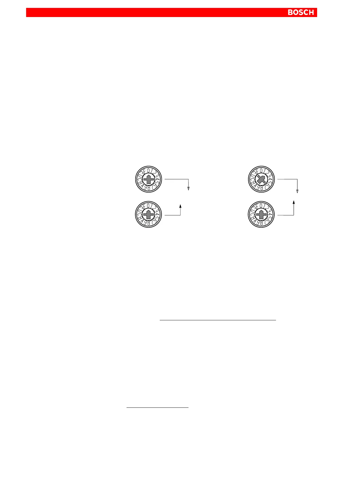
Axis address
Rotary switches S2 and S3 on the individual inverters are used to set the axis
address as a 2-digit hexadecimal value.
Each axis address may appear only once on a CAN bus!
S2
S3
Address __ __ (hex)
S2
S3
Address 02 (hex)
Example:
The hexadecimal value set at these switches is entered as a decimal
value under ”CAN input” of rho machine parameter 401, thus defining
the assignment between the inverter and the axes of the kinematics
(cf. section 2.4).
Baud rate
Set the desired baud rate on rotary switch S4.
rho3: 1000 kBaud (no other setting permitted)
rho4.1: admissible baud rates, depending on the length of the CAN
bus:
S4 Baud rate CAN bus length
0 1000 kBaud 25 m
2 500 kBaud 100 m
3 250 kBaud 100 m
4 125 kBaud 100 m
9 to F 1000 kBaud 25 m
In rho4, the baud rate is stored in machine parameter P30 (default
value: 1000 kBaud).
Mode
Set rotary switch S5 to the value ”1”.
S5 CAN mode
0 CANopen
1 CANrho