Diagnoses
6–4
1070 066 037-101 (00.02) GB
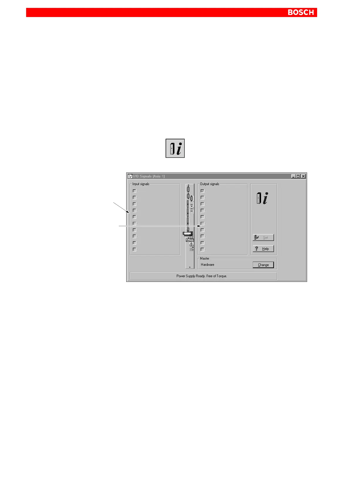
6.3 Displaying I/O signals
The DSS shows you
the signals assigned to the digital inputs and outputs of the inverter, and
the current status of these signals.
For the assignment of individual signals to the digital inputs and outputs of
the inverter, please refer to section 4.2.8 on page 4–8 ff.
Select the menu sequence:
DIAGNOSES I/O SIGNALS, or
click on the
command button in the DSS basic image and then
select ”I/O Signals”.
Display of all input signals con-
figured in P-0-2000.
The current status of the sig-
nals is derived from P-0-2001.
Display of all output signals con-
figured in P-0-2002.
The current status of the signals
is derived from P-0-2003.
The DSS indicates a HIGH level by the ”” character in the checkbox.
Dimmed checkboxes indicate that the corresponding bit has not been as-
signed to a signal in P-0-2001.
The data display is updated in the intervals set for the ”Module status dis-
play” (cf. page 6–3).