IN3 IN4IN1 IN2
1st entry (signal no. 1)
2nd entry (signal no. 2)
Initial commissioning
4–12
1070 066 037-101 (00.02) GB
Example 1 on parameter setting
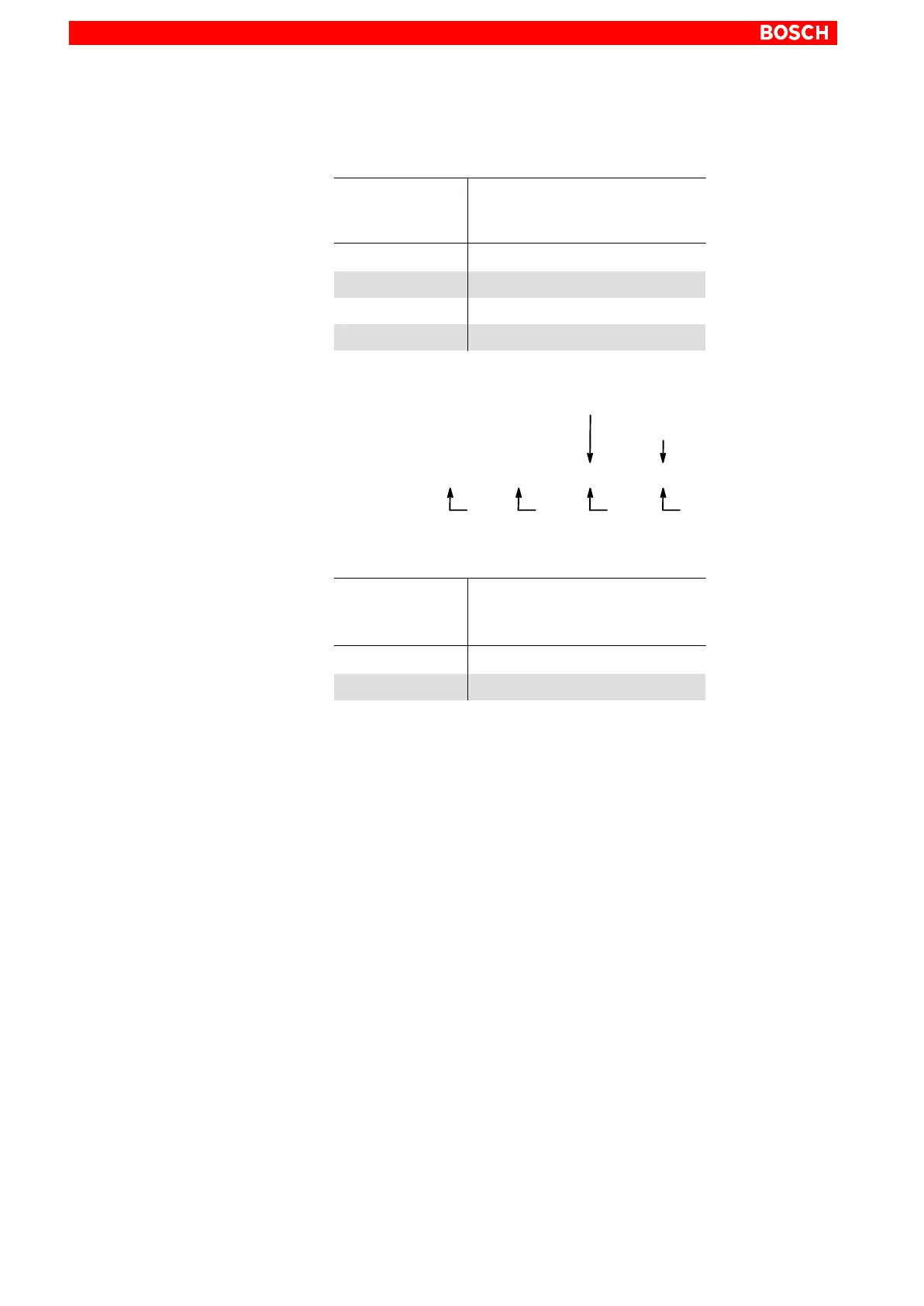
A 4-step torque reduction with the following maximum torques is to be imple-
mented via digital inputs IN3 and IN4:
No. 2
(IN4)
No. 1
(IN3)
+24 V
0 V 0 V
0 V
+24 V 0 V
+24 V+24 V
10% of M
max
25% of M
max
50% of M
max
100% of M
max
Input signal
active torque limit value
(weighting in percent)
Required parameters:
S-0-0092: 10
S-1-0092: 25
S-2-0092: 50
S-3-0092: 100
P-0-2000: S-0-0000,S-0-0000,S-0-0217,S-0-0217
Example 2 on parameter setting
A 2-step torque reduction with the following maximum torques is to be imple-
mented via digital input IN1 alone:
No. 1
(IN1)
+24 V
0 V 10% of M
max
100% of M
max
Input signal
active torque limit value
(weighting in percent)
Required parameters:
S-0-0092: 10
S-1-0092: 100
P-0-2000: S-0-0217...
(1st entry for IN1)
4.2.11 Torque reduction via rho4 (automatic/manual mode)
Changing over from automatic to manual mode on rho4 will initiate a param-
eter set change-over in the drive.
For configuration, only the desired maximum torques are entered in the fol-
lowing parameters:
S-0-0092: maximum torque for automatic mode
S-1-0092: maximum torque for manual mode
For values S-1-0092 < S-0-0092, the parameter set change-over will re-
sult in a torque reduction.
Execute the ”Save main memory” command.