Initial commissioning
4–9
1070 066 037-101 (00.02) GB
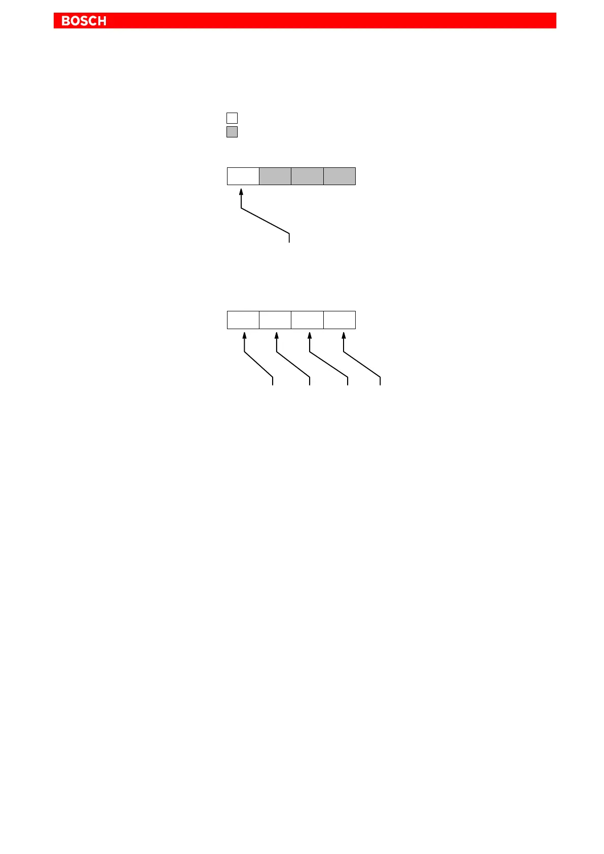
Please note for P-0-2002 (outputs), that only OUT1 can be freely assigned
parameters. Example:
OUT4OUT3OUT2OUT1
P-0-2002=
<1.Par>
Parameters can be set for output
Output is permanently assigned, no parameters can be set.
P117
P-0-2002=S-0-0331
When designing the list in P-0-2000 (inputs), please note the following as-
signments:
IN4IN3IN2IN1
P-0-2000=
<1.Par>
,
<2.Par>
,
<3.Par>
,
<4.Par>
P-0-2000=S-0-0000,S-0-0000,S-0-0217,S-0-0217
Gaps in the signal configuration should be filled with S-0-0000.
Example 1:
If only IN4 is to be assigned, program P-0-2000 as follows:
P-0-2000=0,0,0,
<Par.>
Example 2:
If only IN3 is to be assigned, program P-0-2000 as follows:
P-0-2000=0,0,
<Par.>
Execute the ”Save main memory” command.
By entering P-0-2550 (CANrho control word) in P-0-2002 (outputs), the
status of OUT1 is influenced by the rho.
By entering P-0-2551 (CANrho diagnostics class) in P-0-2000 (inputs),
the respective input is transmitted to the digital rho interface.
rho parameter P36 is used to specify the addresses to which the out-
puts and inputs of the drives are mapped on the rho’s internal PLC in-
terface.