VG4 Modular Camera Series Installing the Pendant Arm Wall, Corner, and Mast (Pole) Mounts | en 23
Bosch Security Systems, Inc. Installation Manual F.01U.162.025 | 6.0 | 2010.03
6. Route the 24 VAC outgoing power supply wires into the VG4-PA0 power supply box
through the conduit fitting on the left side of the box.
7. Cut and trim the 24 VAC power and ground wires with sufficient slack to reach their
connector terminal in the box, but not so long as to be pinched by or to obstruct closing
the cover door.
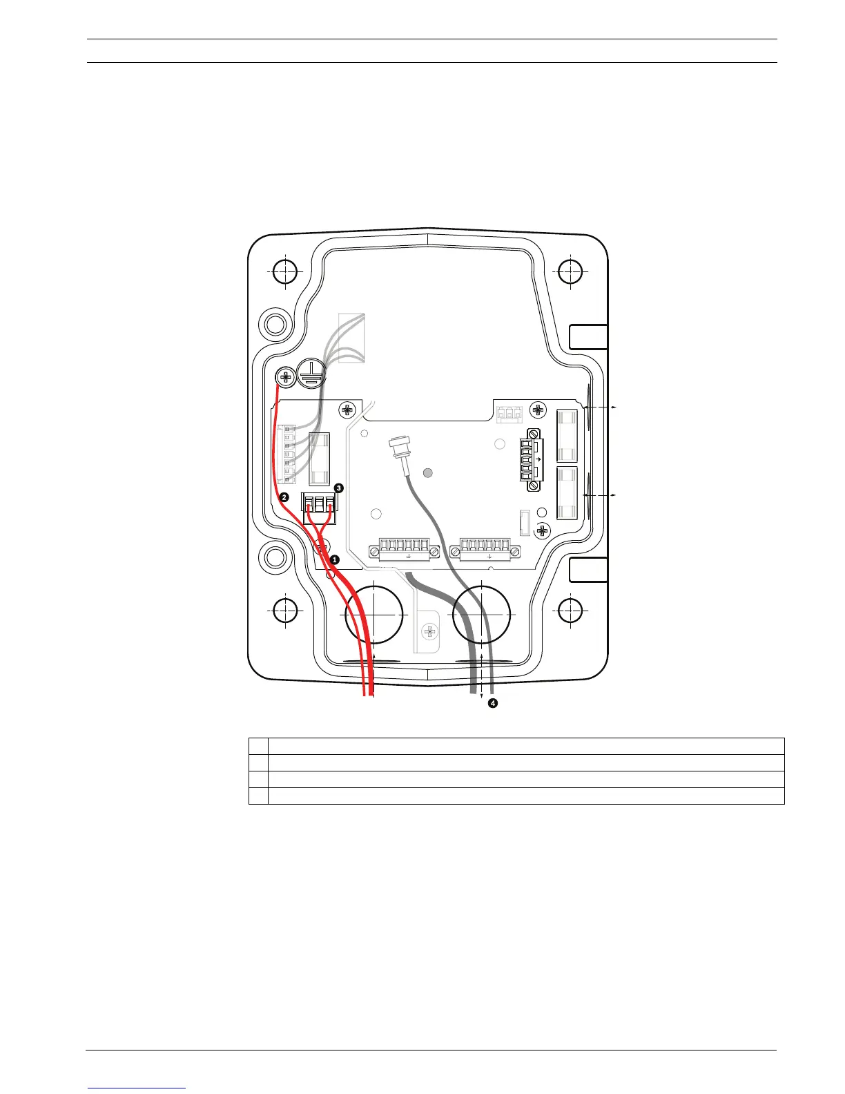
8. Attach the supplied 3-pin power plug to the incoming 24 VAC power wires in the box, as
illustrated below.
Figure 2.8 VG4-PA0 Power Supply Box
9. Follow the instructions in Section 2.6 Attach Pendant Arm to Power Supply Box, page 24, to
continue the installation.
1 Incoming 24 VAC Power Supply Wires (from VG4-PSU1/VG4-PSU2 power supply box)
2Ground Wire
3 P101 Connector
4 Control Data and Video In/Out Wires
GND
+
-
ND
X
+
-
P1
P1
P107
XF102 XF103
XF101
5 4 3 2 1
1
2
101
FUSE
FUSE
FUSE)
 Loading...