68 en | Installing Roof Parapet and Pipe Mounts VG4 Modular Camera Series
F.01U.162.025 | 6.0 | 2010.03 Installation Manual Bosch Security Systems, Inc.
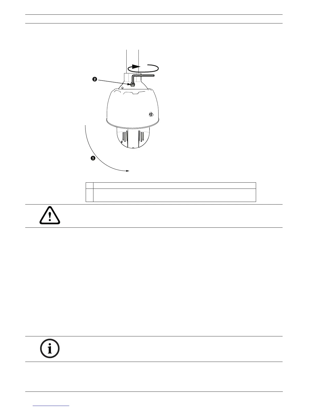
5. Hold the housing in position while tightening the two (2) 5-mm Allen head mounting
screws on top of the housing to 10-12 N-m (90-105 in.-lbs).
Figure 3.19 Tighten Pendant Connection
3.11.5 Make Connections in the Power Supply Box
The following procedure references Figure 3.6, Page 53 to locate the various connectors in the
box and to make the proper connections.
1. Attach the earth ground wire to the grounding screw on the left side of the box.
2. Connect the 24 VAC to Dome plug, installed previously, to its mating connector P107 on
the right side of the box.
3. Connect the 115/230 VAC, 3-pin Power-In plug, installed previously, to its matting
connector P101 on the left side of the box.
Connections for Fiber Optic Models
The following procedure references Figure 3.6, Page 53.
1. If installing a Fiber Optic model, attach the incoming ST fiber plug to its mating
connector on the Fiber Optic Module in the power box.
2. Connect the video BNC connector from the dome to the Fiber Optic Module BNC
connector.
3. Connect the six (6) control plugs from the dome, installed previously, to the P106 control
I/O connector in the Power Supply Box.
1 Rotate down to engage dome connector.
2 Tighten the two (2) mounting screws to a minimum torque of 10-12 N-m
(90-105 in.-lbs).
CAUTION!
You must tighten the two mounting screws to a minimum torque of 10-12 N-m (90-105 in.-lbs)
to ensure a proper seal between the arm and the housing.
NOTICE! A BNC barrel connector (not supplied) is required to connect the male BNC of the
dome to the male BNC connector of the Fiber Optic Module.
 Loading...