VG4 Modular Camera Series Installing the Pendant Arm Wall, Corner, and Mast (Pole) Mounts | en 15
Bosch Security Systems, Inc. Installation Manual F.01U.162.025 | 6.0 | 2010.03
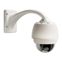
2.1.2 Description
Chapter 2 details how to install an AutoDome Pendant Arm to a wall, a corner, or to a mast
(pole). Any variations to the installation procedures are noted.
See Chapter 3 for a Roof (Parapet) or Pipe mount installation or Chapter 4 for an In-Ceiling
mount installation.
2.1.3 Tools Required
– 5 mm Allen wrench (supplied)
– Small, straight-blade screwdriver - 2.5 mm (0.1 in.)
– No. 2 Phillips screwdriver
– Socket wrench and 9/16-in. socket
– Banding tool (Bosch P/N TC9311PM3T) - if installing a mast (pole) mount
– 3/4 in. (20-mm) NPS right angle conduit connector - if installing a mast (pole) mount with
a VG4-ARMPLATE
– Pin-in Torx tool (supplied) or a T25 pin-in Torx driver (for Pressurized Environmental
Housing)
– Dial-indicator Torque Screwdriver (for Pressurized Environmental Housing)
2.2 Pre-installation Checklist
1. Determine the location and distance for the Power Supply Box based on its voltage and
current consumption.
You may choose to route the main power supply through an intermediate VG4 power
supply box (VG4-PSU1 or VG4-PSU2) before connecting the power to the pendant arm
power supply box (VG4-PA0). See Section 5 Cable and Wire Standards, page 85, for wiring
information and distances.
2. Use only UL listed liquid tight strain reliefs for conduits to the Power Supply Box to
ensure that water cannot enter the box. You must use water tight conduits and fittings to
meet NEMA 4 standards.
3. Route all rough wiring including: power, control, video coax, alarms I/O, relay I/O, and
fiber optic cabling. See Section 5 Cable and Wire Standards, page 85, for video and control
protocol methods.
4. Choose the appropriate AutoDome model (indoor or outdoor) for the environment in
which it will be used.
5. If this AutoDome installation utilizes the AutoTracker feature, refer to
Section A Installation Notes for AutoTracker, page 101, before mounting the AutoDome.
WARNING!
Power and I/O cabling must be routed separately inside different permanently earthed metal
conduits.
WARNING!
Install external interconnecting cables in accordance to NEC, ANSI/NFPA70 (for US
application) and Canadian Electrical Code, Part I, CSA C22.1 (for CAN application) and in
accordance to local country codes for all other countries.
Branch circuit protection incorporating a 20 A, 2-pole Listed Circuit Breaker or Branch Rated
Fuses are required as part of the building installation. A readily accessible 2-pole disconnect
device with a contact separation of at least 3 mm must be incorporated.
 Loading...