78 en | Installing the In-Ceiling Mount VG4 Modular Camera Series
F.01U.162.025 | 6.0 | 2010.03 Installation Manual Bosch Security Systems, Inc.
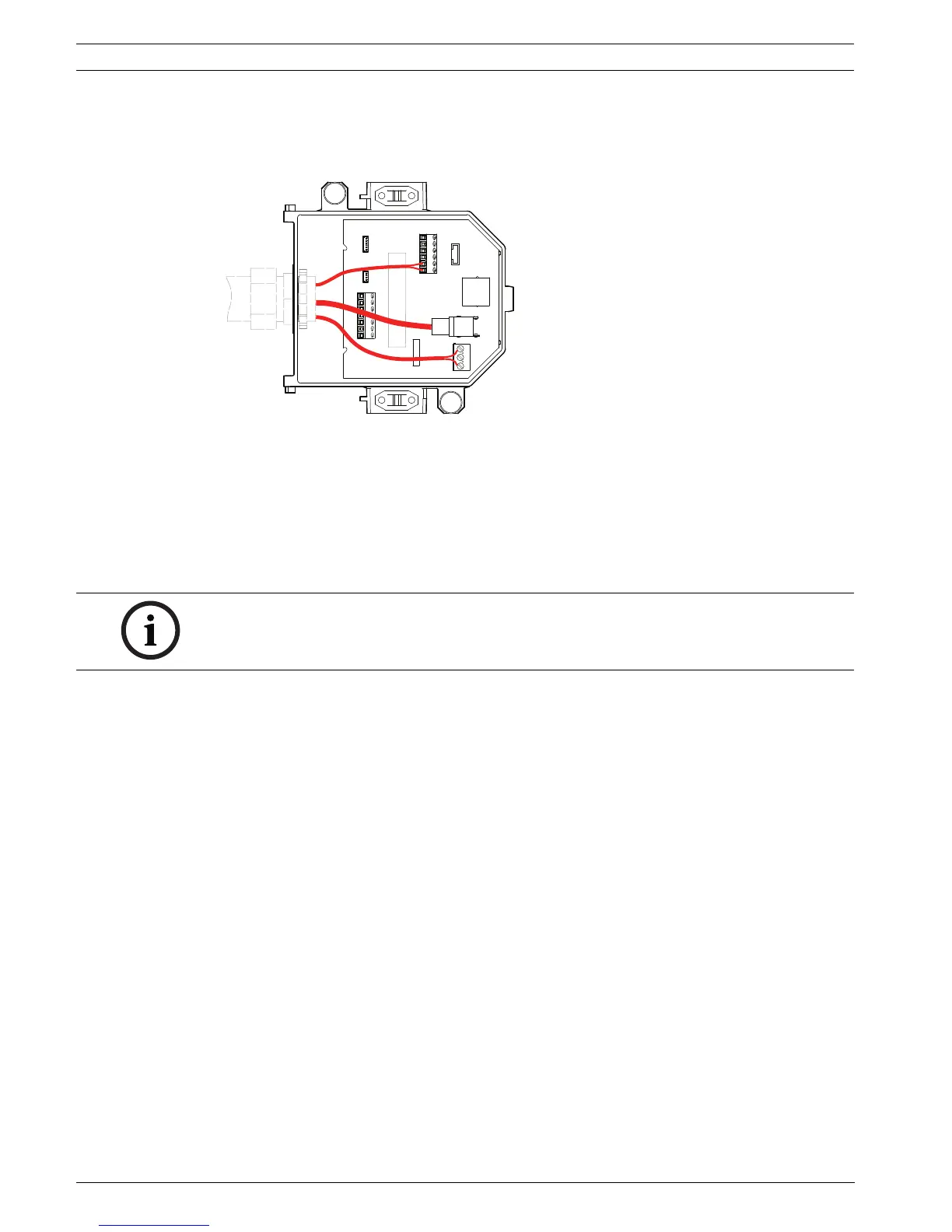
4.6 Wire the Interface Box
The Interface Box can be wired through the top or side. Use the supplied rubber plug to seal
the hole which will not be used to route wires.
Figure 4.6 Interface Box Connections
After routing all video, control, power, and alarm wires:
1. Attach a 3/4-inch NPS (20-mm) conduit fitting to the hole in which you bring in the wires.
Be sure to thread the inside nut to the conduit fitting.
2. Route the video, control, power, and alarm wires through the conduit fitting and into the
Interface Box.
3. Cut and trim the wires allowing for sufficient slack to their respective terminals in the
box.
4. Attach the video and control data in/out wires to their respective terminals in the
Interface Box. See Table 4.1, Page 80, for terminal connections.
5. If using UTP for video or Ethernet, you must attach an RJ45 connector plug to the
incoming UTP cable and connect it to its matting connector J101 in the Interface Box.
See Section 5 Cable and Wire Standards, page 85 for specifications.
6. Connect the 24 VAC power wires to the P101 connector in the Interface Box.
DATA IN/OUT
ALARM IN
P105
P104
P102
P103
ANALOG IN RELAY
ALARMS
OUT
J101
J102
24VAC
24VAC
P101
SIG GND
TXD (-)
RXD (+)
+ C
- C
NC
NO
COM
AGND
A2
A1
FIBER OPTICS
J103
ETHERNET
OR UTP
VIDEO
DOME
POWER
COAX
VIDEO
A3
A4
A5
A6
A7
AGND
AGND
OUT3
OUT2
OUT1
NOTICE! If installing the dome to a drywall ceiling, allow enough wire to make the
connections in the Interface Box below the ceiling. See Figure 4.6, Page 78, for connector
locations and Table 4.1, Page 80, for wire connections.
 Loading...