VG4 Modular Camera Series Table of Contents | en 3
Bosch Security Systems, Inc. Installation Manual F.01U.162.025 | 6.0 | 2010.03
Table of Contents
1Safety 6
1.1 Important Safety Instructions 6
1.2 Safety Precautions 8
1.3 Important Safeguards for Pressurized Units 8
1.4 Important Notices 8
1.5 Customer Support and Service 12
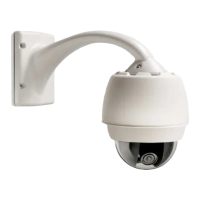
2 Installing the Pendant Arm Wall, Corner, and Mast (Pole) Mounts 13
2.1 Unpacking 13
2.1.1 Parts List 13
2.1.2 Description 15
2.1.3 Tools Required 15
2.2 Pre-installation Checklist 15
2.3 Mount Power Supply Box 16
2.4 Route Wires and Attach Connectors 17
2.4.1 Power Supply Box Connections 20
2.5 Route Power through Intermediate Power Supply Box 21
2.6 Attach Pendant Arm to Power Supply Box 24
2.7 Make Connections in Power Supply Box 25
2.8 Installing the VG4-A-ARMPLATE 27
2.8.1 Attach the Pendant Arm to the Mounting Plate 28
2.8.2 Route and Connect Wires to a Power Supply Box 29
2.9 Assemble Pendant in Packing Box 31
2.10 Attach Pendant to Arm and Tighten 33
2.11 Installing the Pressurized Environmental Housing 35
2.11.1 Important Installation Safeguards 35
2.11.2 VG4 Pressurized Environmental Housing 35
2.11.3 Required Equipment 36
2.11.4 Attaching the Housing to the Arm 37
2.11.5 Calibrating the Pressure Sensor 38
2.11.6 Attaching the Bubble to the Housing 39
2.11.7 Pressurizing the Housing 41
2.11.8 Servicing the VG4 Pressurized Environmental Housing 41
3 Installing Roof Parapet and Pipe Mounts 42
3.1 Unpacking 42
3.1.1 Parts List 42
3.1.2 Description 44
3.1.3 Tools Required 44
3.2 Pre-installation Check List 44
3.3 Mount Power Supply Box 45
3.3.1 Attach Cover Door 46
3.4 Route Wires and Attach Connectors 47
3.4.1 Wiring the Power Supply Box 49
3.4.2 Wiring the Fiber Optic Model 49
3.4.3 Power Supply Box Connections 51
 Loading...
