24 en | Installing the Pendant Arm Wall, Corner, and Mast (Pole) Mounts VG4 Modular Camera Series
F.01U.162.025 | 6.0 | 2010.03 Installation Manual Bosch Security Systems, Inc.
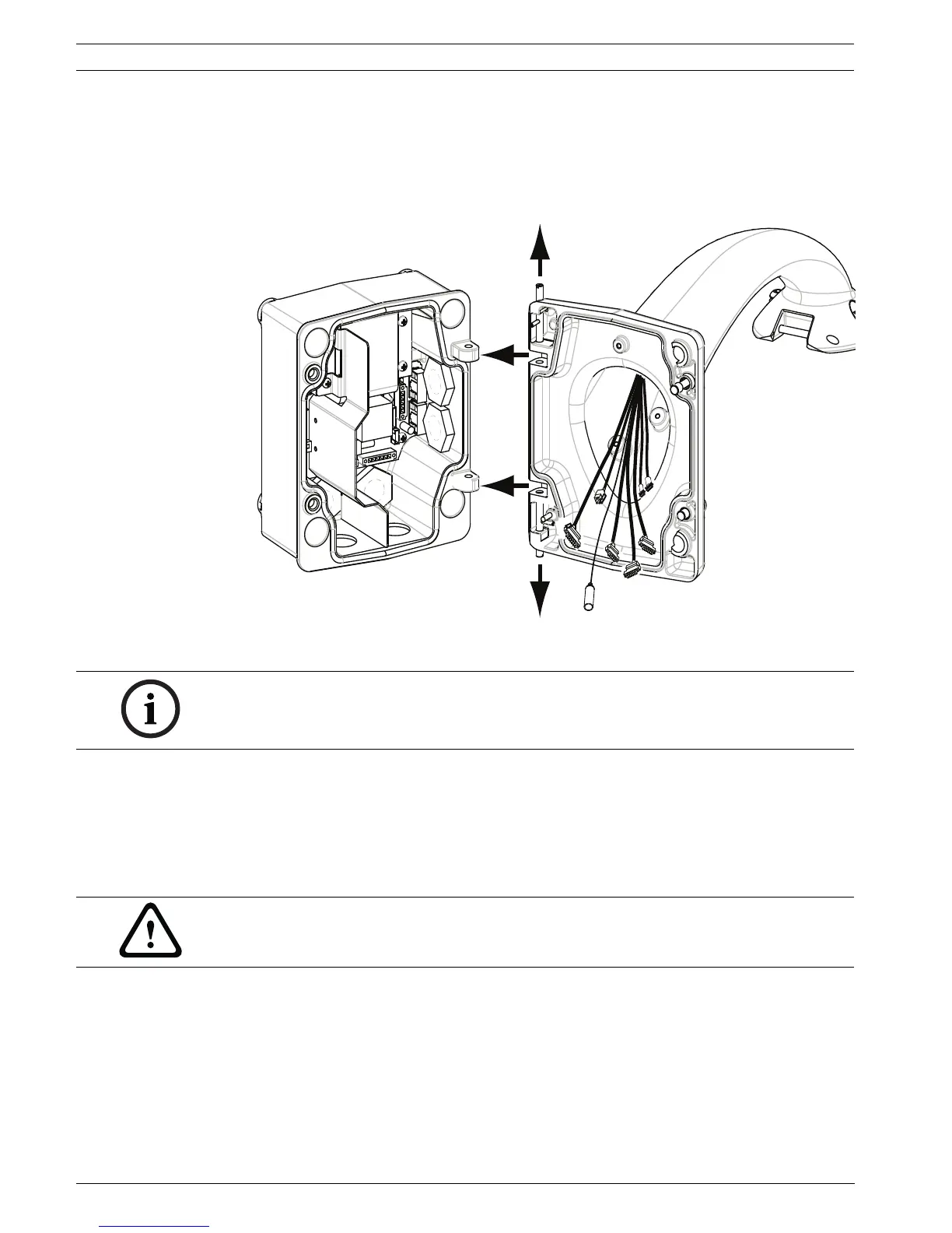
2.6 Attach Pendant Arm to Power Supply Box
The bottom hinge pin of the Pendant Arm is provided with a Hinge Pin Stop to hold the hinge
open while attaching the arm to the Power Supply Box.
1. Compress the bottom hinge pin by pushing the pin lever downward and rotating it
behind the Hinge Pin Stop.
Figure 2.9 Pendant Arm to Power Box Hinge Alignment
2. Open the top hinge by pushing its pin lever up and holding it.
3. While continuing to hold the top hinge pin open and align the top and bottom hinges of
the Pendant Arm to their mating points on the Power Supply Box. See Figure 2.9, above,
for an illustration.
4. Once you have the hinges aligned, release the top hinge pin to engage its mating hinge on
the power box. Then release the bottom hinge pin from the Hinge Pin Stop to lock the
Pendant Arm to the Power Supply Box.
NOTICE! Both Hinge Pins must be fully compressed to open (unlock) the hinges of the
Pendant Arm and before proceeding to the next step.
WARNING!
Serious injury or death can occur if the hinge pins of the Pendant Arm are not fully engaged
(locked) to the Power Supply Box. Exercise caution before releasing the Pendant Arm.
 Loading...