80 en | Installing the In-Ceiling Mount VG4 Modular Camera Series
F.01U.162.025 | 6.0 | 2010.03 Installation Manual Bosch Security Systems, Inc.
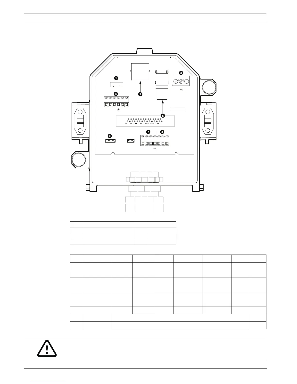
4.6.1 Interface Box Connections
The following figure is a detailed illustration of the In-ceiling Interface box.
Figure 4.8 In-ceiling Interface Box
The following table summarizes the pin connectors and their function:
Table 4.1 Interface Box Wire Terminals
1 Fiber Optics 5 Coax Video
2 Ethernet or UTP Video 6 Alarm In
3 Dome Power 7 Analog In
4 Data In/Out 8 Relay
No. Connector Pin 1 Pin 2 Pin 3 Pin 4 Pin 5 Pin 6 Pin 7
P103 Alarms In Alarm 3 Alarm 4 Alarm 5 Alarm 6 Alarm 7 AGND
P102 Alarms Out Alarm 1 Alarm 2 Alarm 3 GND
P104 Analog Relay Relay
N.O.
Relay
COM
Relay
N.C.
Earth Alarm 1 Alarm 2 Ground
P105 Data In/Out C-
(BiPhase)
C+
(BiPhase)
Earth
Ground
RXD (+)
(RS-232/485)
TXD (-)
(RS-232/485)
Signal
Ground
P101 24 VAC Line Earth Neutral
J102 Video BNC Connector Input
J101 UTP/Ethernet Connector Input
P105
P104
P102
P103
J101
J102
24VAC
24VAC
P101
SIG GND
TXD (-)
RXD (+)
C +
C -
NC
NO
COM
AGND
A2
A1
J103
A3
A4
A5
A6
A7
AGND
AGND
OUT3
OUT2
OUT1
WARNING!
24 VAC Class 2 power supply only.
 Loading...