96 en | Alarms and Relay Connections VG4 Modular Camera Series
F.01U.162.025 | 6.0 | 2010.03 Installation Manual Bosch Security Systems, Inc.
6 Alarms and Relay Connections
6.1 Alarm Inputs
The AutoDome provides seven alarm inputs. Each input can be activated by dry contact
devices such as pressure pads, passive infra-red detectors, door contacts, and similar
devices. The table below summarizes the size and distance wires.
Table 6.1 Alarm wire guide
You wire alarms either Normally Open (N.O.) or Normally Closed (N.C.), and must program the
alarm inputs N.O. (the default) or N.C. through the AutoDome main menu.
The AutoDome incorporates two (2) types of alarms: Non-supervised and Supervised. In
addition to transmitting an alarm condition, a supervised alarm also transmits a tamper
condition. Depending on how the alarm is configured, a short or a break in the alarm’s circuit
can trigger the tamper signal.
6.2 Configuring Supervised Alarms (inputs 1 and 2)
To configure Alarm 1 or 2 (pin 5 or 6) for supervision, you must install a 2.2 K end-of-line
resistor in the circuit. Then, you program the alarms through the AutoDome main menu to
either Normally Open Supervised (N.O.S.) or Normally Closed Supervised (N.C.S.).
6.2.1 Configuring a Normally Open Supervised Alarm
1. Install a 2.2 K end-of-line resistor in the alarm circuit.
2. Connect the alarm wires to input 1 or 2 (pin 5 or 6) and to the ground (pin 7) at the
AutoDome.
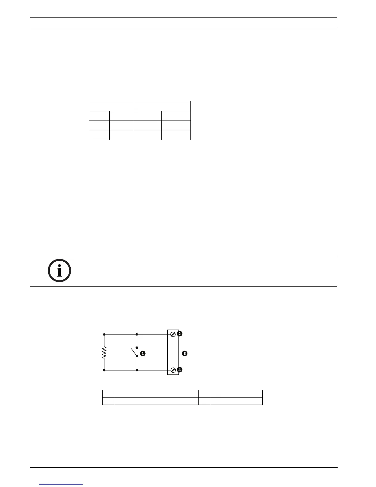
Figure 6.1 N.O.S. - Normally Open Supervised Connections
Wire Size Maximum Distance
AWG mm feet meters
22 0.644 500 152.4
18 1.024 800 243.8
NOTICE! Only Alarms 1 and 2 (pins 5 or 6) can be configured for supervision. Once a
supervised alarm is programmed it does not need to be enabled to indicate a tamper
condition.
1 Dry Contact 3 Dome Connector
2 Alarm 1 or 2 only (Pin 5 or 6) 4 Ground (Pin 7)
 Loading...