92 en | Cable and Wire Standards VG4 Modular Camera Series
F.01U.162.025 | 6.0 | 2010.03 Installation Manual Bosch Security Systems, Inc.
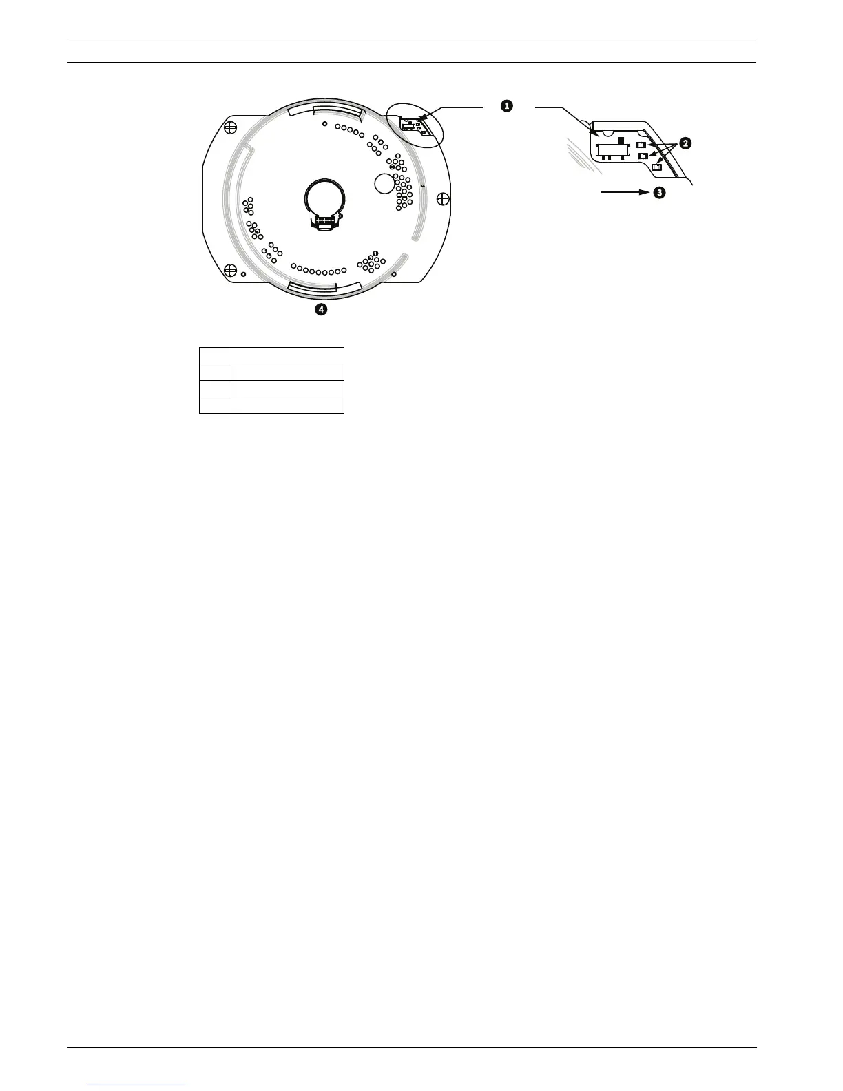
Figure 5.7 Position of CPU Switch for RS485 Operation
5.5 Fiber Optic Module with an RS232/RS422 Controller
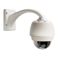
An AutoDome with a fiber optic module is prewired to operate with Biphase signals only. This
section describes the procedures necessary to control a VG4 series AutoDome fitted with a
fiber optic kit using an RS232 controller or a Pelco® RS422 controller.
To control a VG4 Series Autodome from an RS232 or from a Pelco RS422 controller you must
run control wires from the controller to an LTC 4629 head-end fiber optic module.
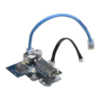
5.5.1 Connecting to an LTC 4629 Head End Data/Video Transceiver
1. Connect the RS232 cable (TxD from the controller) to the RS232 RxD port (pin 1) of the
LTC 4629.
2. Connect the ground wire of the controller to Pin 2 on the LTC 4629.
1 Switch Location
2LEDs
3RS485
4CPU Module
 Loading...