VG4 Modular Camera Series Installing Roof Parapet and Pipe Mounts | en 47
Bosch Security Systems, Inc. Installation Manual F.01U.162.025 | 6.0 | 2010.03
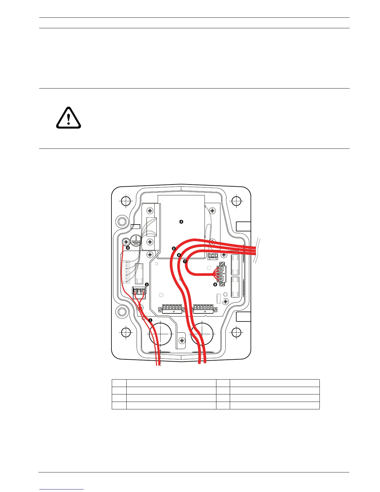
3.4 Route Wires and Attach Connectors
Power wires must be routed to the left (front) side of the Power Supply Box through a
separate conduit. All video, control, and alarm wires must be routed through a second conduit
to the right side of the box. See Section 5 Cable and Wire Standards, page 85 for methods of
transmitting video and data, and for wire specifications.
There are two possible methods to route the video, control, and alarm wires:
– One is to route the video, control, and alarm wires through the conduit fitting on the right
(front) side of the Power Supply Box and out to the AutoDome Interface Board.
Figure 3.3 VG4-A-PSU1 or VG4-A-PSU2 Power Supply Box
WARNING!
External interconnecting cables are to be installed in accordance to NEC, ANSI/NFPA70 (for
US application) and Canadian Electrical Code, Part I, CSA C22.1 (for CAN application) and in
accordance to local country codes for all other countries.
Branch circuit protection incorporating a 20 A, 2-pole Listed Circuit Breaker or Branch Rated
Fuses are required as part of the building installation. A readily accessible 2-pole disconnect
device with a contact separation of at least 3 mm must be incorporated.
1 120 VAC/230 VAC Power In 5 Video Wire
2 P101 Connector 6 Control Wire
3 Ground Connection 7 24 VAC Power Out
4 Transformer 8 P107 Connector
GND TXD
RXD
C+
C-GND TXD
RXD
C+
C-
P101
P106 P105
P107
XF102 XF103
XF101
5 4 3 2 1
1
2
J101
(LED)
HTR DOME
24V NC 24V
FUSE
FUSE
FUSE
 Loading...