VG4 Modular Camera Series Installing the Pendant Arm Wall, Corner, and Mast (Pole) Mounts | en 39
Bosch Security Systems, Inc. Installation Manual F.01U.162.025 | 6.0 | 2010.03
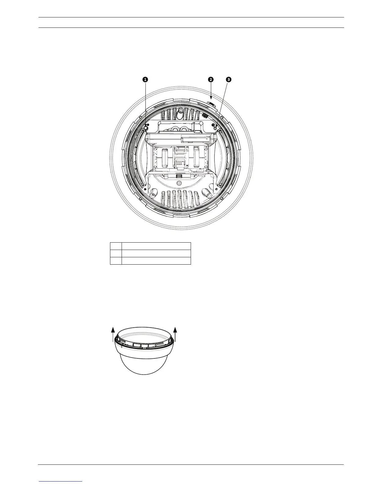
3. Using a thin screwdriver press and hold the red calibration switch, located on the
opposite side of the LED.
Once the sensor is calibrated and the data is permanently stored, the LED shuts off and
you can release the calibration switch.
Figure 2.22 Location of the Calibration Switch
4. Turn the power off to the VG4 unit.
2.11.6 Attaching the Bubble to the Housing
1. Remove the bubble from the box and then remove the bubble from the protective plastic
bag.
2. Disengage the four tabs from the white trim skirt ring that surrounds the bubble. Then,
move the trim skirt ring towards the bubble opening to remove.
Figure 2.23 Bubble with Trim Skirt Ring
3. Discard the trim skirt ring. It is not needed for the Pressurized Environmental Housing
installation.
4. Clean the inside of the bubble. Refer to Section 7 Bubble Handling and Cleaning, page 100,
for cleaning instructions and for recommended products.
5. Clean the groove inside the rubber bubble gasket with pressurized air to remove debris.
Then, using alcohol, clean the groove to remove oil and grease.
6. Insert the sealing edge of the bubble into the groove in the rubber bubble gasket.
1 Calibration Switch
2 Schrader Fill Valve
3LED
 Loading...