94 en | Cable and Wire Standards VG4 Modular Camera Series
F.01U.162.025 | 6.0 | 2010.03 Installation Manual Bosch Security Systems, Inc.
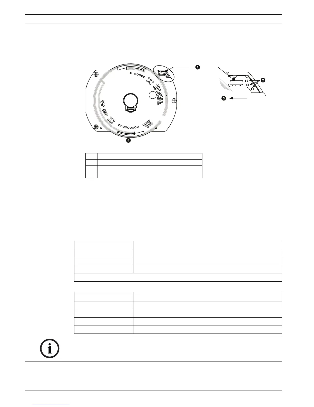
10. Ensure that the VG4 AutoDome is set to receive RS232 commands.
– Remove the bubble from the VG4 AutoDome housing.
– Locate the protocol switch on the CPU board.
– Ensure that the protocol switch is in the left position for RS232 operation.
Figure 5.9 Position of CPU Switch for RS232 Operation
11. Return the bubble to the AutoDome housing.
12. Return power to the power supply box.
5.6 Audio Cables
The VG4 AutoDome with Ethernet module is capable of receiving line input audio signals and
transmitting it over a network. The audio signal is transmitted one-way and in sync with the
video signals.
Audio Line Input Specifications
Wire Specifications
1 Switch Location
2LEDs
3 Move Switch to the left for RS232 Operation
4CPU Module
Max. Input Voltage 5.5 Vpp
Impedance 9K ohm
Sample Rate 8 K Hz, 16 Bit, mono
Shield Bare copper braid: 95% coverage
Internal gain level adjustment is available
Wire Type
Coax
3
(recommended)
Distance 10 m (33 ft)
Gage 22 AWG to Biphase connector (P105/P106)
Shield Bare copper braid: 95% coverage
Center conductor Stranded bare copper
NOTICE! Separate the audio cables from the AC power lines to avoid noise.
 Loading...