VG4 Modular Camera Series Installing the Pendant Arm Wall, Corner, and Mast (Pole) Mounts | en 29
Bosch Security Systems, Inc. Installation Manual F.01U.162.025 | 6.0 | 2010.03
2. Open the top hinge by pushing its pin lever up and holding it.
Note: Both Hinge Pins must be fully compressed to open (unlock) the hinges of the
Pendant Arm and before proceeding to the next step.
3. While continuing to hold the top hinge pin open, align the top and bottom hinges of the
Pendant Arm to their mating points on the Mounting Plate. See Figure 2.12, above, for an
illustration.
4. Once you have the hinges aligned, release the top hinge pin to engage its mating hinge on
the Mounting Plate. Then release the bottom hinge pin from the Hinge Pin Stop to lock
the Pendant Arm to the Mounting Plate.
2.8.2 Route and Connect Wires to a Power Supply Box
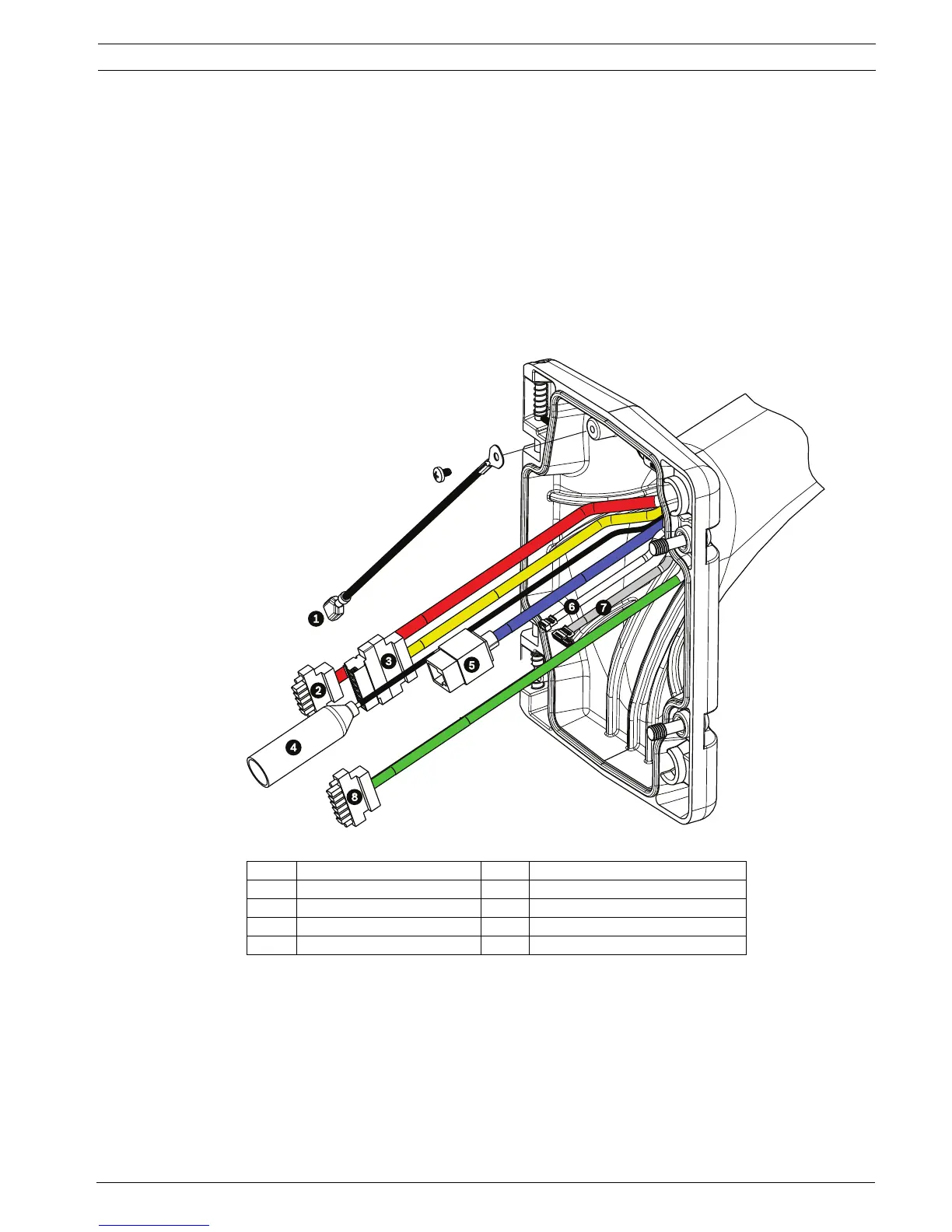
The illustration below depicts the power and control cables connected to the Pendant Arm:
Figure 2.13 Pendant Arm Cables
Cable Cable Cable Cable
1 Grounding Strap (black) 5 UTP Video/Ethernet (blue)
2 24 VAC Power (red) 6 Alarm Outputs (white)
3 Relay Contacts (yellow) 7 Alarm Inputs (gray)
4 Coax Video (black) 8 Serial Communications (green)
 Loading...