VG4 Modular Camera Series Cable and Wire Standards | en 91
Bosch Security Systems, Inc. Installation Manual F.01U.162.025 | 6.0 | 2010.03
RS485 (2-wire (shielded), half-duplex, differential, multi-drop (32 nodes), 4000 ft cable limit)
RS485 is capable of controlling a true multi-drop network and is specified for up to 32 drivers
and 32 receivers on a single 2-wire bus. The AutoDome uses the 2-wire mode, although RS485
can be connected in a 2- or 4-wire mode.
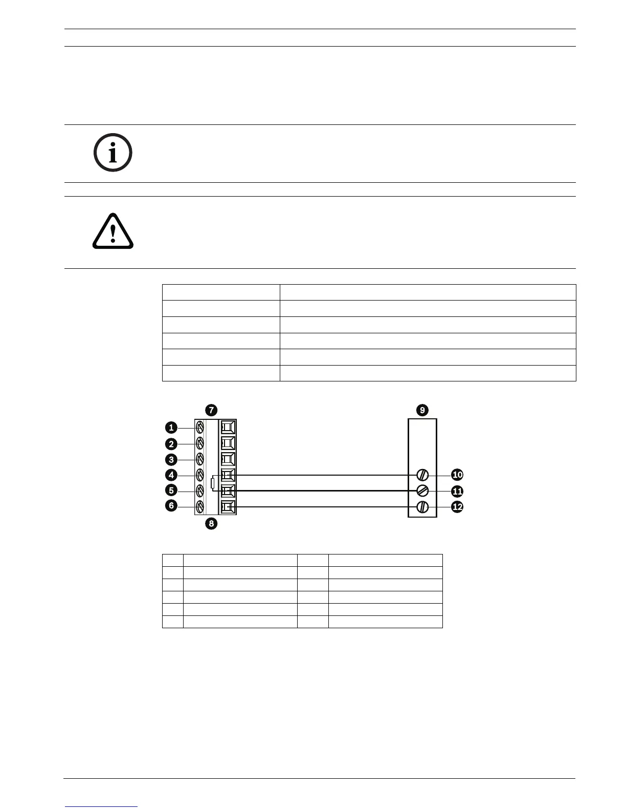
The following figure illustrates the connections for RS485 connections.
Figure 5.6 Connections for RS485 Operations
NOTICE!
The wire shield must be tied to signal at both ends, if 2-wire twisted pair is used. After
connecting the wires for RS485 operation, make sure the slide switch on the main board to
the camera head is positioned toward the LEDs (default).
CAUTION!
Bosch recommends that multiple RS485 connections be arranged as a connected series of
point-to-point (multi-dropped) nodes, as a line or as a bus. It is not recommended to arrange
RS485 connections as a star, ring, or as a multiple-connected network. Star and ring
topologies may cause signal reflections or excessively low or high termination impedance.
Wire Type 2-wire shielded twisted pair
Distance 1219 m (4000 ft)
Maximum Baud Rate 57.6 kb
Gage 0.511 mm (24 AWG)
Wire Impedance 120 W
Slide Switch Toward LEDs (factory default)
1 C- (Biphase) 7 AutoDome Data In/Out
2 C+ (Biphase) 8 P105/P106 Connector
3 Earth Ground 9 Head End RS485
4 RxD 10 Data +
5 TxD 11 Data -
6 Signal Ground 12 Ground
 Loading...