VG4 Modular Camera Series Installing the In-Ceiling Mount | en 79
Bosch Security Systems, Inc. Installation Manual F.01U.162.025 | 6.0 | 2010.03
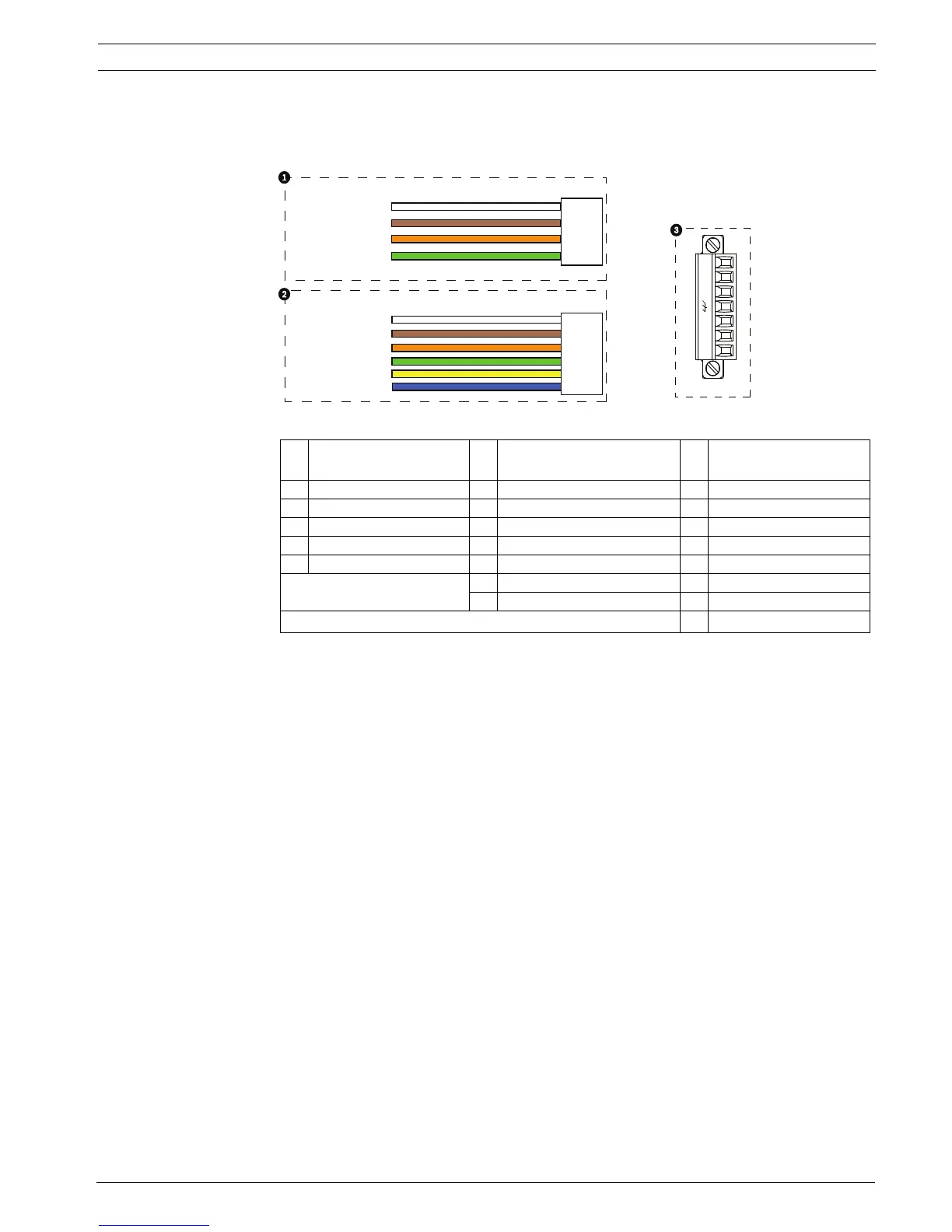
7. To connect alarm inputs and outputs, attach the supplied 6-pin Alarms In and the 4-pin
Alarms Out connector plugs with flying leads to the appropriate alarm wires. Then
connect the plugs to their mating connectors P103 and P102 in the Interface Box.
Figure 4.7 Alarm and Relay Connector Plugs
8. To connect supervised alarms and relays, attach the appropriate wires to their terminals
on the P104 connector on the Pipe Interface Board. See Section 6 Alarms and Relay
Connections, page 96 for more details on wiring alarms.
1 4-pin Alarm Connector
(P102)
2
*
6-pin Alarm In Connector
(P103)
3 7-pin Relay Connector
(P104)
Pin Description Pin Description Pin Description
1 Alarm Out 1 1 Alarm In 3 1 Normally Open
2 Alarm Out 2 2 Alarm In 4 2 COM
3 Alarm Out 3 3 Alarm In 5 3 Normally Closed
4 Alarm Ground 4 Alarm In 6 4 Earth Ground
5 Alarm In 7 5 Analog Alarm 1
6 Alarm Ground 6 Analog Alarm 2
* Low Voltage TTL (3.3V) can also be used.
7Ground
1
1
2
3
4
5
6
2
3
4
N.O. COM N.C. A1 GND A2
1
PIN
PIN
P102
P103
P104
WHITE
ORANGE
BROWN
GREEN
WHITE
ORANGE
BROWN
GREEN
YELLOW
BLUE
2
3
4
5
6
7
 Loading...