7850-Install-IG101 Installation Guide
Brocade
®
7850 Extension Switch Hardware Installation Guide
Monitoring the Device
The power-on self-test (POST) performs diagnostic tests every time the device is powered on, rebooted, or reset. The
LEDs on the device indicate system activity and status.
Interpreting Port-Side LEDs
System activity and status can be determined through the activity of the LEDs on the switch.
The LEDs have three possible states: no light, a steady light, and a flashing light. Flashing lights may be slow, fast, or
flickering. The lights are green or amber for all ports.
Sometimes, the LEDs may flash any of the colors during boot, POST, or other diagnostic tests. This flashing is normal;
it indicates a problem only if the LEDs indicate an unhealthy state after all boot processes and diagnostic tests are
complete.
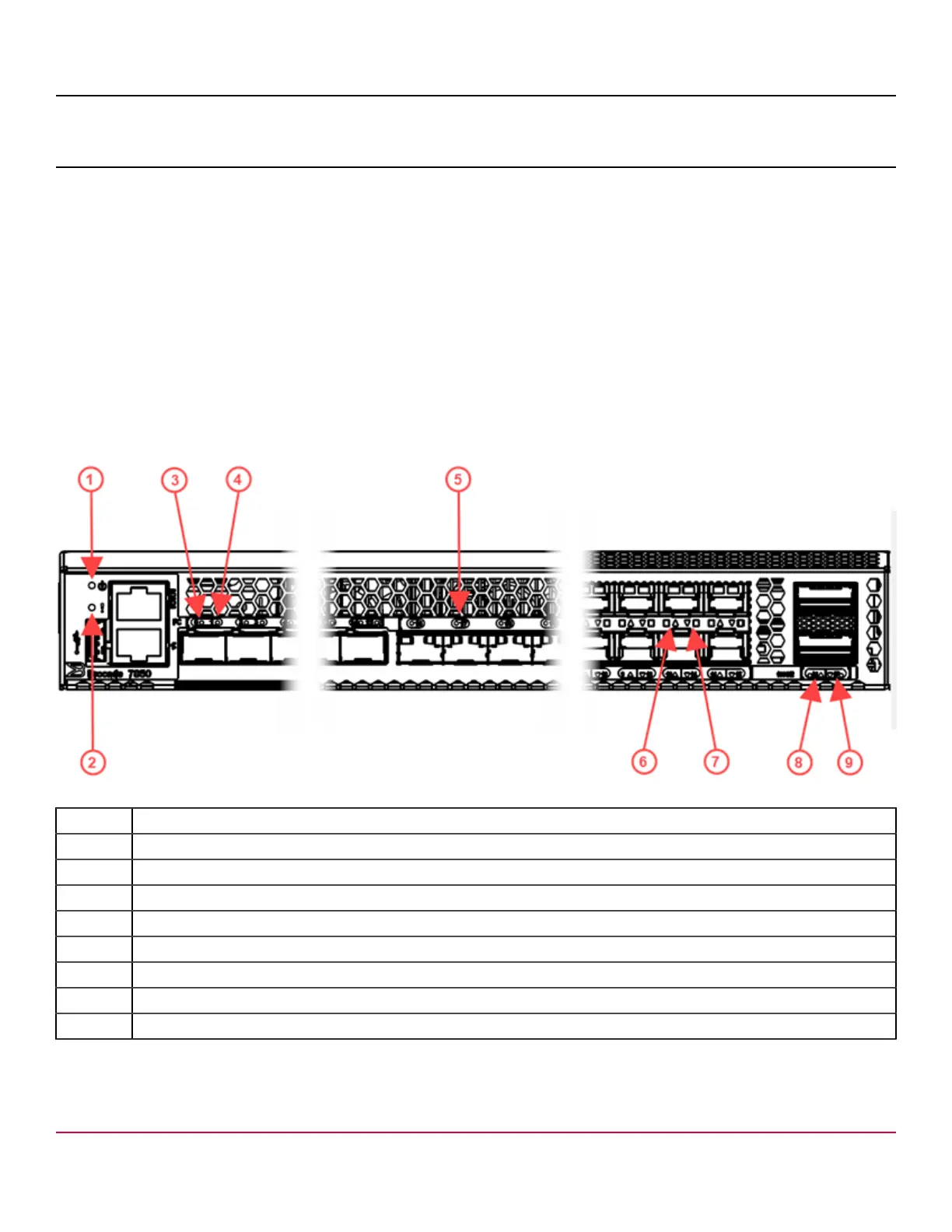
Figure 39: Brocade 7850 Extension Switch Port-Side LEDs
1. System Power LED
2. System Status LED
3. SFP-DD FC Port 0 Status LED
4. SFP-DD FC Port 1 Status LED
5. SFP+ FC Port 17 Status LED
6. Ethernet SFP+ Port 10 Status LED (upper)
7. Ethernet SFP+ Port 14 Status LED (lower)
8. 100 GbE QSFP Port 16 Status LED (upper)
9. 100 GbE QSFP Port 17 Status LED (lower)
7850-Install-IG101
67