Brocade MLXe Series Hardware Installation Guide 209
53-1003030-01
Replacing fan assemblies
6
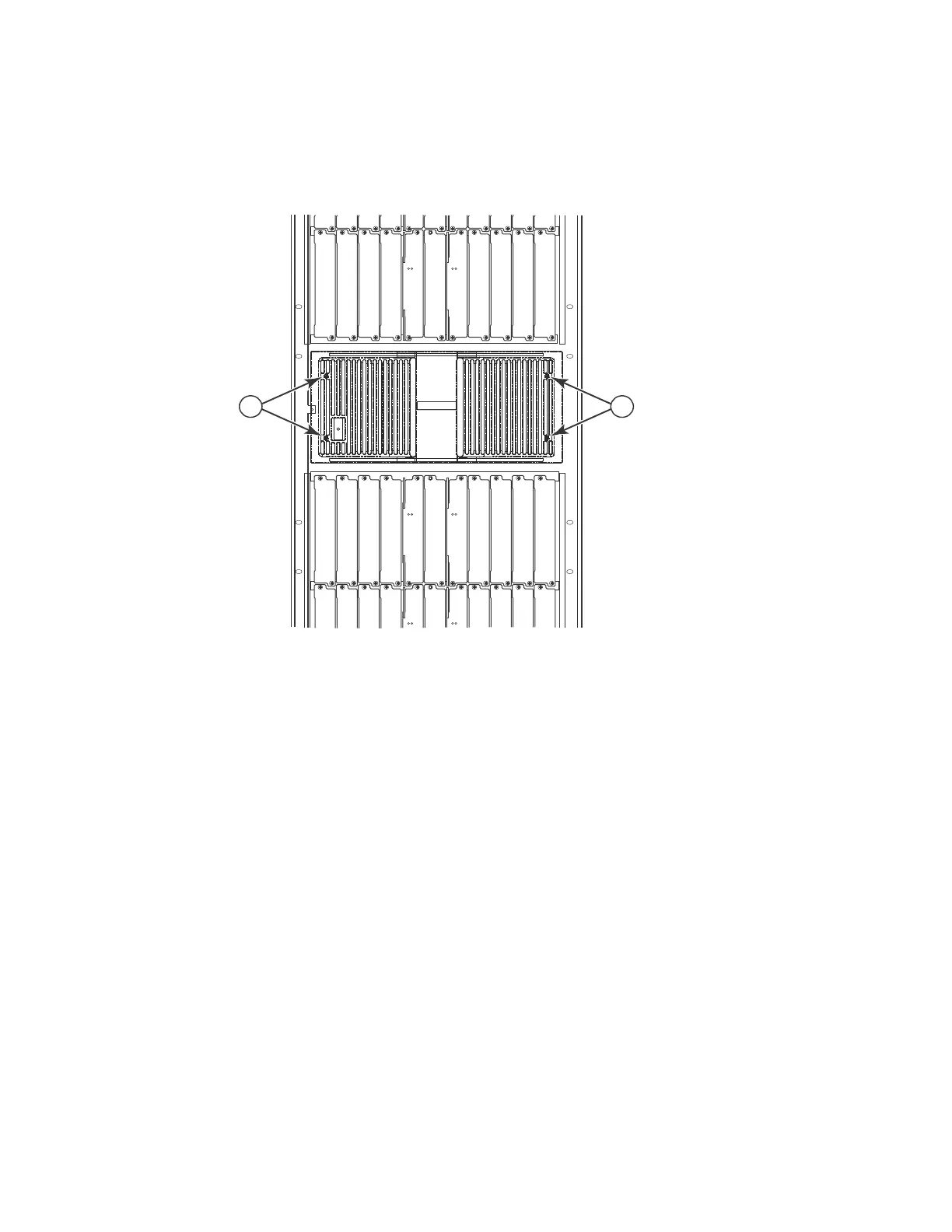
1. From the front of the router, remove the air inlet cover by unscrewing the four captive screws
with a 7/64 inch hex head screwdriver, as shown in Figure 117.
FIGURE 117 32-slot router air inlet panel.
2. Remove the old air filter by pulling it straight out from the router, as shown in Figure 118.
3. Insert a new filter, being careful that it aligns within the narrow channel.
4. Repeat steps 2 and 3 to replace the second filter.
5. Replace the air inlet cover and tighten the four captive screws to secure the air filter to the
router.
1Captive screws
Pwr
Active
Pwr
Active
Pwr
Active
Pwr
Active
1 1
 Loading...