24 Brocade MLXe Series Hardware Installation Guide
53-1003030-01
Router modules
1
• Arrow-shaped LEDs in center horizontal strip for all ports. LEDs to the left support the top
ports, LEDs to the right (pointing down) support the bottom ports.
• 24 1 Gbps fiber ports
Table 11 describes the LEDs for the BR-MLX-1GFx24-X and BR-MLX-1GFx24-X interface modules.
For a list of SFP optics supported for the BR-MLX-1GFx24-X and BR-MLX-1GFx24-X interface
modules, refer to the latest version of the Brocade Optics Family Data Sheet, available online in the
following location:
http://www.brocade.com/downloads/documents/data_sheets/product_data_sheets/optics-famil
y-ds.pdf
Power supply requirements for BR-MLX-1GFx24-X and BR-MLX-1GFx24-X-ML interface modules
For power supply requirements for BR-MLX-1GFx24 and BR-MLX-1GFx24-X ML (24-port 1 Gbps)
fiber interface modules, refer to Chapter 7, “Hardware Specifications”.
20-port 100/1000 Ethernet interface module
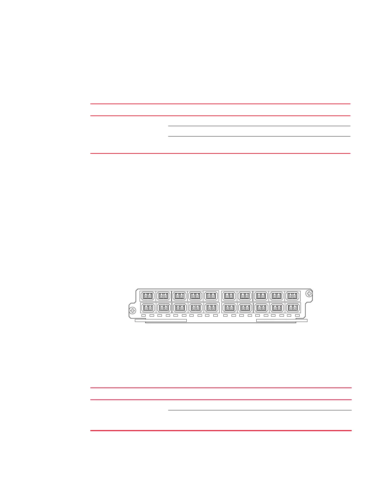
Figure 16 shows the front panel of the 20-port 100/1000 Gbps Ethernet SFP interface module.
FIGURE 16 20-port 100/1000 Ethernet module front panel
The front panel includes the following features:
• LEDs to the left support the top ports, LEDs to the right support the bottom ports
• 20 100/1000 Ethernet SFP ports
Table 12 describes the LEDs for the 20-port 100/1000 Ethernet module
TABLE 11 BR-MLX-1GFx24-X and BR-MLX-1GFx24-X fiber module LEDs
Position State Meaning
Arrow-shaped LEDs in center
horizontal strip between ports.
Left LEDs support upper ports.
Right LEDs support lower ports.
Solid green A link has been established.
Green blinking The port is transmitting and receiving packets.
Off No link exists, and the port is not transmitting or receiving
packets.
TABLE 12 20-port 100/1000 Ethernet module LEDs
Position State Meaning
Below each Ethernet port.
(Left-side LED supports port in
top row. Right-side LED supports
port in bottom row.)
On or blinking The port is transmitting and receiving packets.
Off for an extended period The port is not transmitting or receiving packets.
 Loading...