Brookeld Engineering Labs., Inc. Page 29 Manual No. M13-167-A0415
Theprocessofselectingaspindleandspeedforanunknownuidisnormallytrialanderror. An
appropriate selection will result in measurements made between 10-100 on the instrument %
torque scale.Therearetwogeneralrulesthatwillhelpinthetrialanderrorprocess:
1)Viscosityrangeisinverselyproportionaltothesizeofthespindle.
2)Viscosityrangeisinverselyproportionaltotherotationalspeed.
Inotherwords:tomeasurehighviscosity,chooseasmallspindleand/oraslowspeed.Ifthechosen
spindle/speedresultsinareadingabove100%,thenreducethespeedorchooseasmallerspindle.
Experimentationmayrevealthatseveralspindle/speedcombinations
will produce satisfactory results between 10-100%. When this
circumstanceoccurs,anyofthespindlesmaybeselected.
Non-Newtonianuidbehaviorcanresultinthemeasuredviscosityand
yieldstresschangingifthespindleand/orspeedischanged.Seeour
publication,“MoreSolutionstoStickyProblems”,formoredetails.
When viscosity data must be compared, be sure to use the same
test methodology: namely the same instrument, spindle, speed,
container, temperature and test time.
DV3TLVRheometersareprovidedwithasetoffourspindlesand
a narrow guardleg; DV3TRV Rheometers come with a set of six
spindlesandawiderguardleg;DV3THAandDV3THBRheometers
comewithasetofsixspindlesandno guardleg.(SeeAppendixG
formoreinformationontheguardleg.)
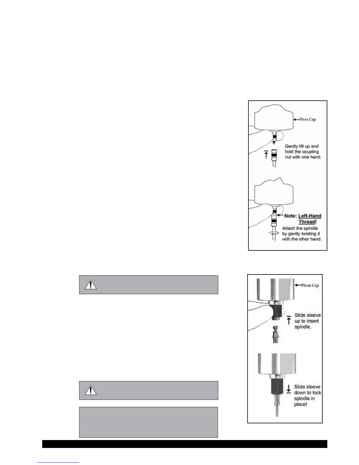
Thespindlesareattachedtotherheometerbyscrewingthemonto
thecouplingnutonthelowershaft(seeFigureIII-4).Notethatthe
spindleshavealeft-handthread.Thelowershaftshouldbesecured
andslightlyliftedwithonehandwhilescrewingthespindletothe
left.Thefaceofthe spindlenutandthematchingsurfaceon the
lowershaftshouldbesmoothandcleantopreventeccentricrotation
ofthespindle.Spindlescanbeidentiedbythenumberontheside
ofthespindlecouplingnut.
ThemotorshouldbeOFF whenever
spindlesarebeingremovedorattached.
IfyourinstrumenthastheEZ-Locksystem,thespindlesareattached
asfollows:
With one hand holdthespindle,whilegentlyraisingthespring-
loadedoutersleevetoitshighestpositionwiththeotherhand,as
shown in Figure III-5. Insert the EZ-Lock SpindleCoupling so
thatthebottomofthecouplingisushwiththebottomoftheshaft,
andlowerthesleeve.Thesleeveshouldeasilyslidebackdownto
holdthespindle/couplingassemblyinplaceforuse.[Spindlescan
beidentiedbyentrycode;lookforthenumberonthesideofthe
EZ-Lockspindlecoupling.]
ThemotorshouldbeOFF whenever
spindlesarebeingremovedorattached.
Note: KeeptheEZ-LockSpindleCouplingand
outersleeveascleanaspossibleandfree
from debris that could become lodged
insidetheadapter.
Figure III-5
Figure III-4