Brookeld Engineering Labs., Inc. Page 48 Manual No. M13-167-A0415
IV.3 Selecting a Spindle/Speed
TheDV3Thasthecapabilityofmeasuringyieldstressoveranextremelywiderange.Forexample,
theDV3TRVcanmeasureuidswithintherangeof0.5-400Pa.Thisrangeisachievedthrough
theuseofseveralvanespindlesovermanyspeeds.SeeAppendixBfordetails.
Theprocessofselectingaspindleandspeedforanunknownuidisnormallytrialanderror. An
appropriate selection will result in measurements made between 10-100 on the instrument %
torque scale.Therearetwogeneralruleswillhelpinthetrialanderrorprocess:
1)Viscosityrangeisinverselyproportionaltothesizeofthespindle.
2)Viscosityrangeisinverselyproportionaltotherotationalspeed.
Inotherwords:tomeasurehighyield,chooseasmallspindleand/oraslowspeed.Ifthechosen
spindle/speedresultsinareadingabove100%,thenreducethespeedorchooseasmallerspindle.
Experimentation may reveal that several spindle/speed combinations will produce satisfactory
resultsbetween10-100%.Whenthiscircumstanceoccurs,anyofthespindlesmaybeselected.
When yield data must be compared, be sure to use the same test methodology: namely the
same instrument, spindle, speed, container, temperature and test time.
VanespindlesareoptionalequipmentandarenotpartofthestandardDV3Tpackage.DV3TLV
Rheometersareprovidedwithasetoffourspindlesandanarrowguardleg;DV3TRVRheometers
comewithasetofsixspindlesandawiderguardleg;DV3THAandDV3THBRheometerscome
withasetofsixspindlesandno guardleg.(SeeAppendixGformoreinformationontheguardleg.)
Do not use the guard leg with vane spindles.
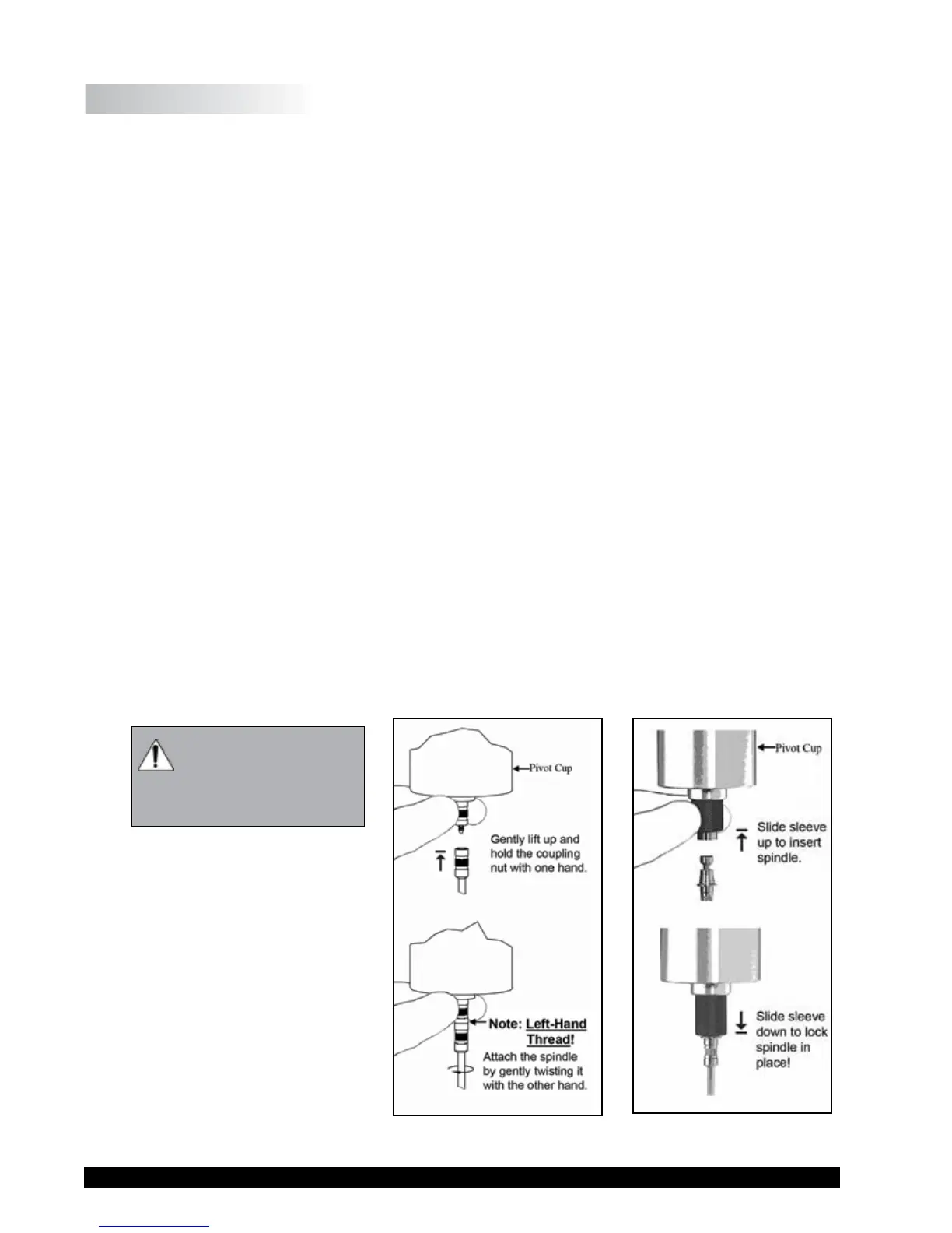
Thespindlesareattachedtotherheometerbyscrewingthemontothecouplingnutonthelower
shaft(seeFigureIV-1).Notethatthespindleshavealeft-handthread.Thelowershaftshould
besecuredandslightlyliftedwithonehandwhilescrewingthespindletotheleft.Thefaceof
thespindlenutandthematchingsurfaceonthelowershaftshouldbesmoothandcleantoprevent
eccentricrotationofthespindle.Spindlescanbeidentiedbythenumberonthesideofthespindle
couplingnut.
IfyourinstrumenthastheEZ-Lock
system,thespindlesareattachedas
follows:
Withonehandholdthespindle,while
gentlyraisingthespring-loadedouter
sleeve to its highest position with
theotherhand,asshowninFigure
IV-2. Insert the EZ-Lock Spindle
Couplingsothatthebottomofthe
couplingisushwiththebottomof
theshaft,andlowerthesleeve.The
sleeveshouldeasilyslidebackdown
toholdthespindle/couplingassembly
The motor should
be OFF whenever
spindles are being
removedorattached.
Figure IV-1 Figure IV-2