3 - 71
Feed module
Modules
Assembly
11
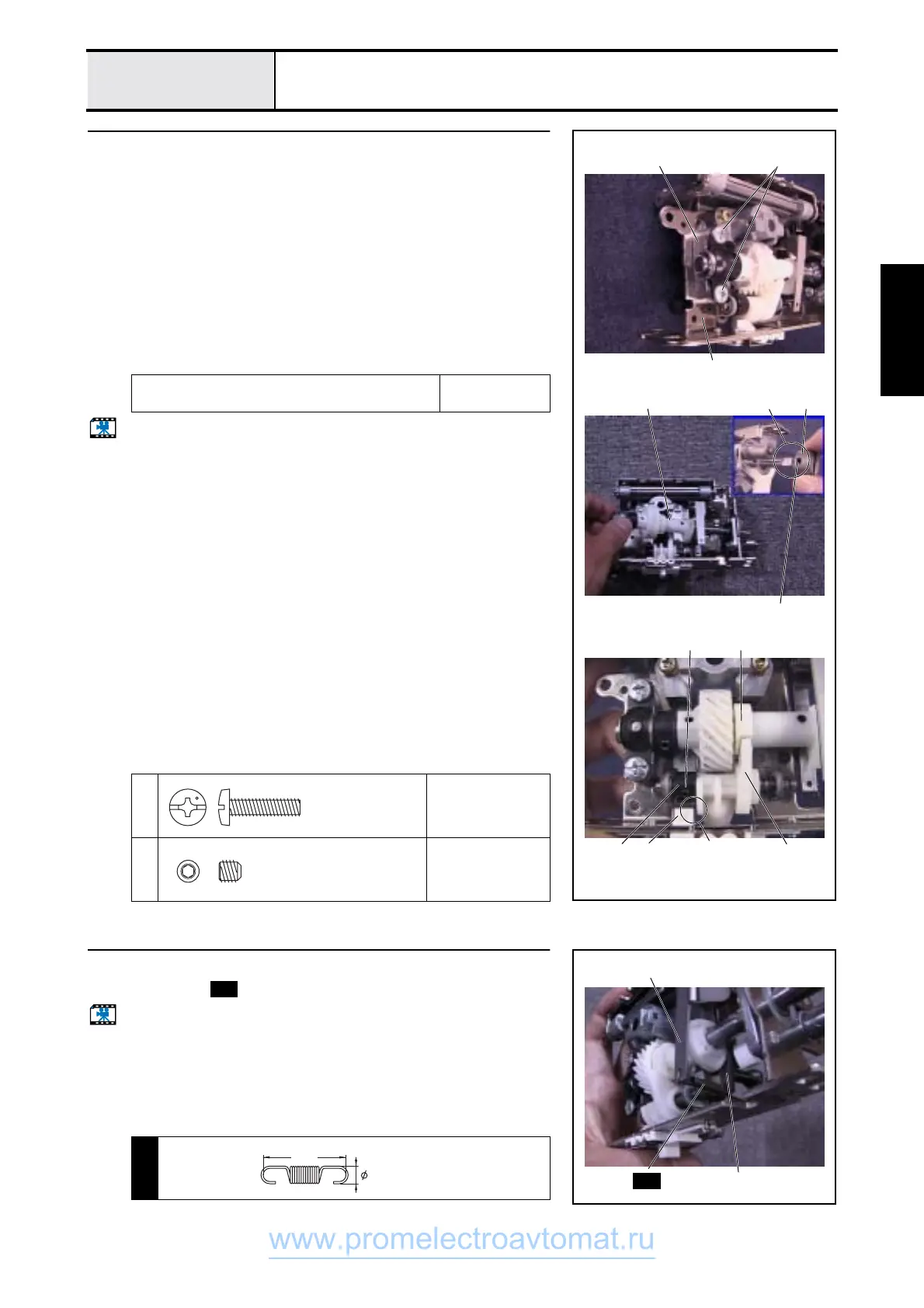
Lower shaft B assy. attachment
1. Attach the bushing supporter A 1 to the feed base 2.
2. Attach the lower shaft B assy. 3.
3. Attach bushing presser A 4 using screws 1 (two).
4. Attach the joint 5 using screws 2 (two).
*Key point
• Align the screw hole 6 in the joint 5 and the D cut 6 in the
lower shaft B.
5. Adjust the right-left position of the set screw collar 0 so that there is a gap
between the vertical lever 7 and the drop knob 8 and so that the vertical
feed cam contact area of the vertical lever 7 does not come off of the
vertical feed cam 9, and fully tighten *screw S15.
Start movie clip (CD-ROM version only)
Lubricate the lower shaft (inserted side of
bushing supporter assy.) with Sewing Lube.
1 – 2 drops
1
Torque
1.18 – 1.57 N
−
m
2
Torque
1.18 – 1.57 N
−
m
1
9
7
1
2
1
2
53 6
8
Leave gap
0
Screw, Bind
M4X16
Color; Silver
Set Screw, Socket (CP
M5X5
Color; Black
12
Support spring attachment
1. Attach spring to the feed supporting plate assy. 1 and feed arm B 2.
Start movie clip (CD-ROM version only)
S37
1
S12
2
S12
SPRING
XZ0174***
4
18.8
www.promelectroavtomat.ru
 Loading...