4 - 9
Adjustment (Main Unit)
Inspection and
Adjustment
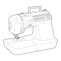
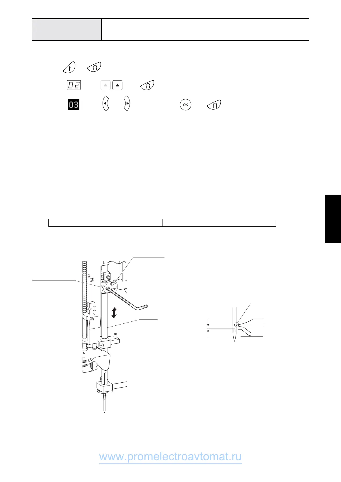
Needle bar height adjustment
1. Attach the operation PCB assy. flat cable and power PCB assy. lead wire connector to the main PCB assy., and
attach the front cover to the arm bed.
2. Press and while turning the power on (the buzzer will sound four times, and test mode will start).
3. <S2>
Select using , press once, and set the needle bar to the left base line position.
<S3>
Select using or , and after pressing press once, and set the needle bar to the left
base line position.
4. Turn off the power.
5. Lower the presser foot lifter.
6. Turn the pulley by hand until the right edge of the needle and the tip of the outer rotary hook meet (pulley turned
counterclockwise).
7. Loosen the set screw (socket (CP) M4X4) in the needle bar block
8. Adjust the height of the needle bar for 1.0 – 1.4 mm between the top of the needle hole and lower edge of the
outer rotary hook tip.
NOTE •Needle hole turned forward
9. Fully tighten set screw (socket (CP) M4X4.
10. Perform 4 - 23 "Adjust the needle thread block."
Set screw, socket (CP) M4X4
torque 0.78 – 1.18 N-m
Needle block
crew, socket 4 × 4
Iron bar
1.0 - 1.4mm
Right edge of needle
and tip meet
www.promelectroavtomat.ru
 Loading...