4 - 16
Adjustment (Main Unit)
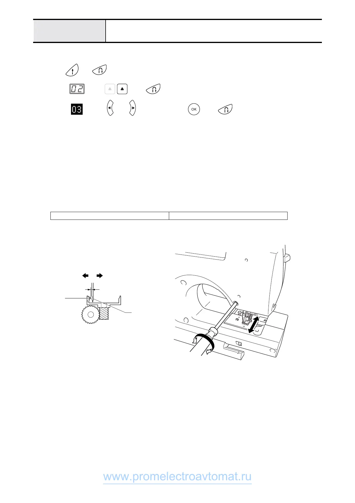
Clearance between the needle and the rotary hook point adjustmen
1. Attach the operation PCB assy. flat cable and power PCB assy. lead wire connector to the main PCB assy., and
attach the front cover to the arm bed.
2. Press and while turning the power on (the buzzer will sound four times, and test mode will start).
3. <S2>
Select using , press three times, and set the needle bar to the right base line position.
<S3>
Select using or , and after pressing , press three times, and set the needle bar to
the right base line position.
4. Turn off the power.
5. Remove screws M4 (two), and remove needle plate A (1).
6. Loosen screw, pan M3X12 (or remove it)
7. Hand turn the pulley until the right edge of the needle and the outer rotary hook tip meet.
8. Adjust the gap between the needle and the outer rotary hook tip (front and back) to 0.1 mm or less using the
tightening depth of the adjusting screw.
9. Install and fully tighten screw, pan M3X12.
10. Attach needle plate A using screws M4 (two).
Screw, pan M3X12,
torque 0.78 – 1.18 N-m
0.1mm or less
Needle
Rear surface
Tip
Front surface
www.promelectroavtomat.ru
 Loading...