5 - 3
Failure Investigation
for Electronic Parts
Failure Investigation for Electronic Parts
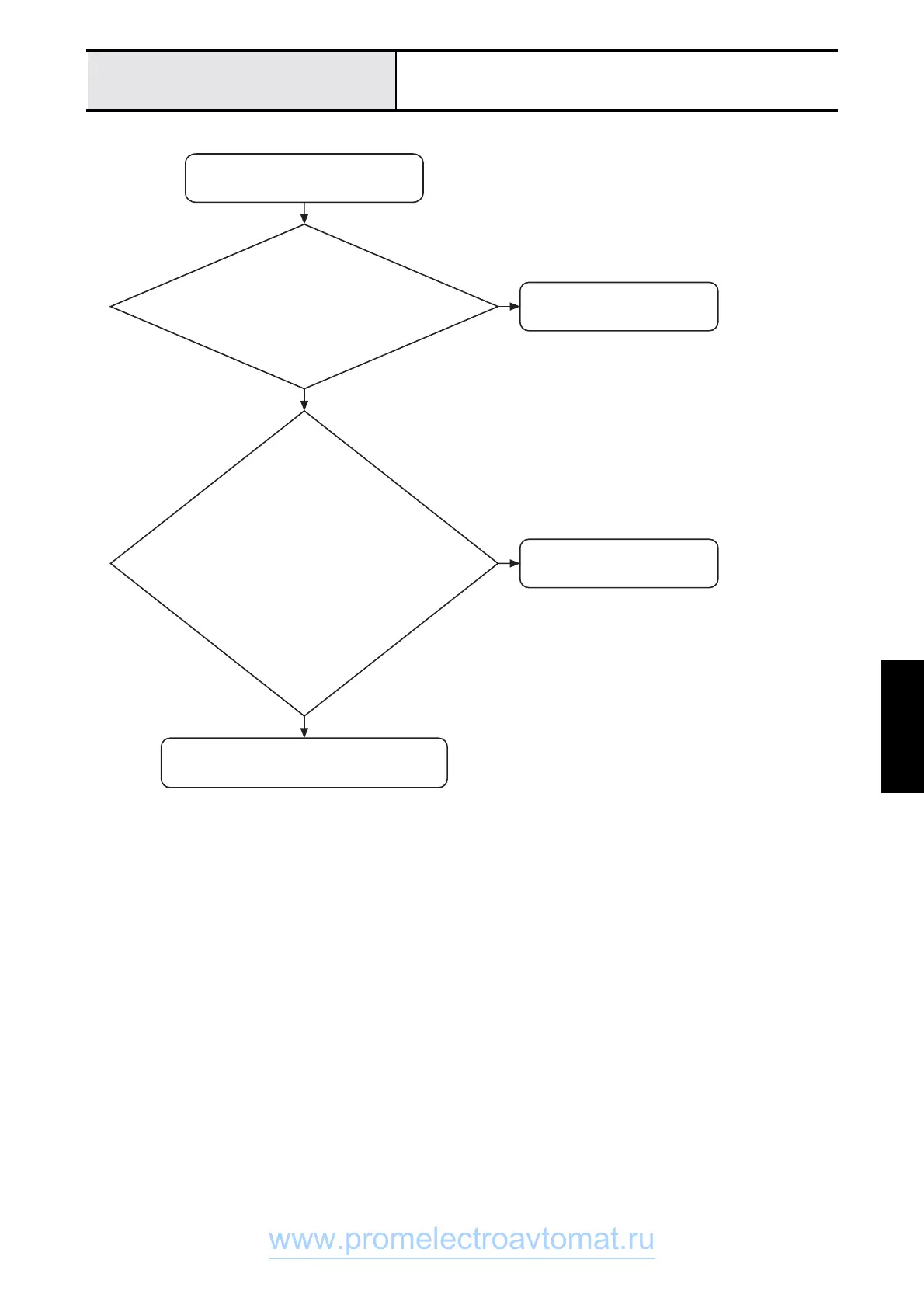
Power cannot be turned on
No LCD display when power is
turned ON
Replace inlet assy.
Replace power PCB assy.
When the inlet assy. connector is disconnected
from the power PCB assy. and the power is
turned ON, is the voltage between the connector
pins 100 - 120V AC or 220 - 240V AC?
With the power PCB connector (CN 13
(S2) or CN14 (S3) main PCB assy.)
disconnected, are the voltages normal
across pins 2-3, pins 4-3 and pins 5-6?
• Pins 2-3 ... 5V DC
• Pins 4-3 ... 26V DC
• Pins 5-6 ... 26V DC
Replace main PCB assy.
N
N
Y
Y
S2 : CS8000 Series
S3 : CS8100 Series
www.promelectroavtomat.ru
 Loading...