3-31
Confidential
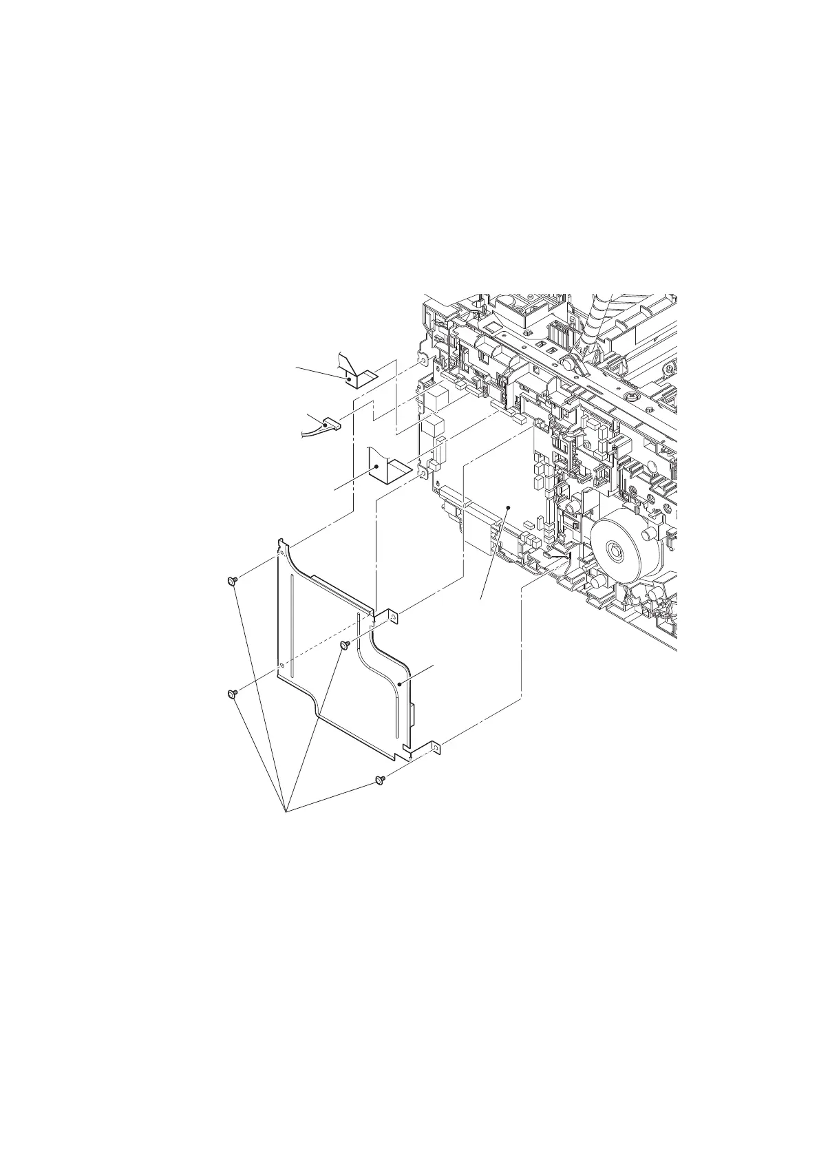
9.9 Top cover ASSY
(1) Remove the four Screw cup M3x8 (black) screws to remove the Main shield cover plate
ASSY.
(2) Disconnect the Panel flat cable (for Touch panel models) or the Panel harness (for Non-
touch panel models) and the LED control flat cable from the Main PCB, and then release
them from the securing fixtures.
Fig. 3-18
Harness routing: Refer to “2. Main PCB, Cartridge sensor relay PCB”.
Screw cup M3x8 (black)
Main shield cover
plate ASSY
Main PCB
LED control flat cable
Panel flat cable
(For Touch panel models)
Panel harness
(For Non-touch panel models)
 Loading...