29II-
9.2.1.4. LCD Check Display
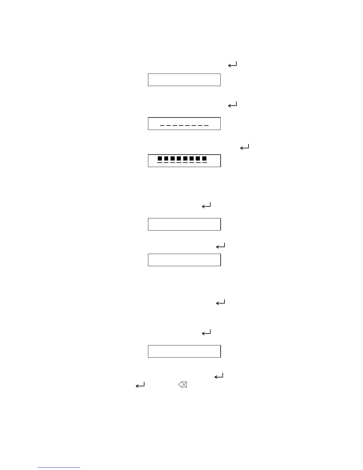
Here, check for missing dots and the display function of the LCD.
The LCD check 1 <Fig. 4> is displayed when depressed “ ” key.
Fig. 4
The LCD check 2 <Fig. 5> is displayed when depressed “ ” key.
Fig. 5
Shifts to “28.2.2 Cassette Inspection Mode” when depressed “ ” key. (Fig. 7 Display)
Fig. 6
9.2.2. Cassette Sensor Inspection Mode “2” Key
Here, ckeck the cassette sensor function.
Display of Fig. 7 is indicated when depressed “ ” key or depressed “2” key in the display
of Fig. 6 (except while in the Key Inspection Mode).
Fig. 7
Shifts to the Key Inspection Mode when depressed “ ” key. (Fig. 8 Display)
Fig. 8
Displays the three sensor SW states. ON: 1, OFF: 0
Touch the sensor switch with the finger tip while checking ON/OFF display.
Shifts to the Key Inspection Mode when depressed “ ” key. (Fig. 9 Display)
9.2.3. Key Inspection Mode “3” Key
Here, check the key input function.
Display of Fig. 9 is indicated when depressed “ ” key or depressed “3” key in the display
of Fig. 8 (except while in the Key Inspection Mode).
Fig. 9
Shifts to the Key Inspection Mode when depressed “ ” key. (Fig. 10 Display)
The “CODE” key, “( )” key”, “BS( )”, “←”, “→” key (1st row) L → R, (2st row) R → L,
(3st row) L → R, 4st row) R → L, (5st row) L → R are depressed sequentially. The key to
depress is displayed (refer to Fig. 10) and the key to depress next is displayed when
depressed correctly while the key to depress next and “X” are displayed when depressed
erroneously. (Fig. 11 Display)
H H H H H H H H
C A S T
All cursor off.
All guidance off.
X X X X X X X X
All cursor on.
All guidance on.
X
All cursor on.
All guidance on.
C A S 0 0 0
K E Y
 Loading...