10 (55) BRUKER BIOSPIN Technical Manual Version 001
Installation and Handling
Mounting the DPP1 PCI Board 2.3
The DPP1 board is intended to be mounted in a PCI environment. The driver is LI-
NUX specific and will only work in an AVANCE III IPSO system.
DSP firmware is loaded from the TopSpin PC via the PCI bus and Ethernet.
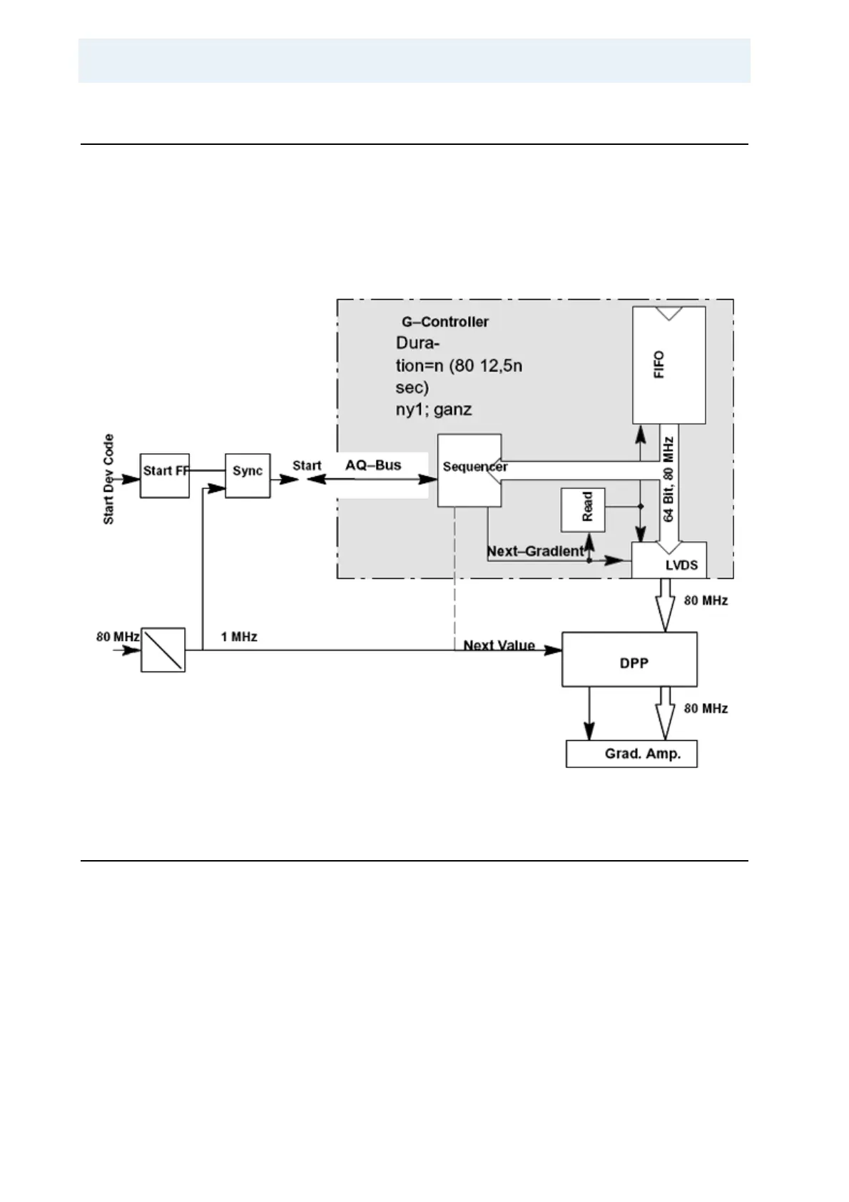
All gradient values are transferred over two 48–bit LVDS interfaces.
The Next–Value (NV) clock signal is attached using a coax cable on the IPSO 19
inch case, or using a PCI connector pin on the IPSO AQS.
Figure 2.1. IPSO Functional Signal Flow
Booting the DPP1 2.4
The boot process starts after turning on the IPSO. The configuration is carried out
beginning with post code “49” and LINUX begins to boot if the post code exceeds
“60”.
Recognition of the DPP1 during booting can be verified using the Web server on
the IPSO or by using a browser on the TopSpin PC. The IPSO IP address, which
is needed by the browser, can be located: in TopSpin, in the Hyper Terminal or in
a shell on the workstation.
In TopSpin:
Type “ha” at the command line to display a dialog for all devices. Click on
IPSO to open a browser with the IPSO’s IP address.