40 (55) BRUKER BIOSPIN Technical Manual Version 001
Description
Input FIFO and Output FIFO, Space CE2 and CE3 5.4.9.4
The LVDS input and output FIFO is a high density synchronous 36 bit FIFO. Only
the lower 32 bits are connected to the EMIF bus of the DSP. If the LVDS words
have a legal valid bit, the information is written into the input FIFO.
The input FIFO and output have a size of 36 bits x 8192 words.
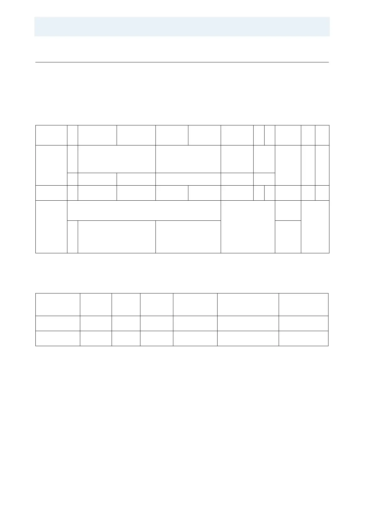
Table 5.32: Bit Allocation at the EMIF Bus
Bit
4
8
47..44 43..38 37..22 21..18 17..6 5 4 3 2 1
Field
P
A
R
MS B Address MS B Data Data
(res)
(res) !LAST !V
A
LI
D
!N
G
ADD<9..6> ADD<5..0> DATA <19..0> gnd gnd
Number
1 4 6 16 4 12 1 1 1 1 1
Connec
ted to
DSP
Data
Bus or
Logic
DSP Data Bus Bit
Not connected
DSP
Bit
Logic
3
1
29..20 19..0 30
Table 5.33: Type of FIFO‘s Used on the DPP1
Local Hex
Address
Size
[KByte]
Word
[Byte]
Type
Bandwidth
[MByte/s]
Type of Controller Identification
Axxx xxxx 128 4 Byte 200 DPP1 H12513F1 Receiver FIFO
Bxxx xxxx 128 4 Byte 200 DPP1 H12513F1 Transmit FIFO