34 (55) BRUKER BIOSPIN Technical Manual Version 001
Description
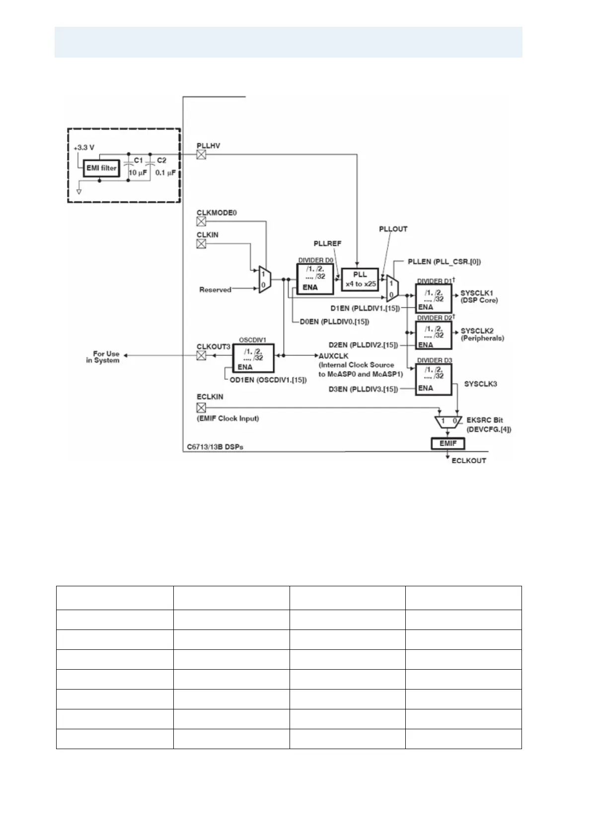
Figure 5.2: Pll Register Structure
All registers must be initialized by software after reset. The PLL controller regis-
ters should be modified only by the CPU, and as soon as possible at the begin-
ning of the program.
Table 5.22: PLL Register Contents
Register Name Address Value Comment
PLLM 0x1B7C110 0xb CLKIN x 11
PLLDIV 0 0x1B7C114 0x8000 Divide by 1
PLLDIV 1 0x1B7C118 0x8000 Divide by 1
PLLDIV 2 0x1B7C11C 0x8001 Divide by 2
PLLDIV 3 0x1B7C120 0x8002 Divide by 3
PLLCSR 0x1B7C100 0x40 Quit reset
PLLCSR 0x1B7C100 0x41 Enable PLL