20 (55) BRUKER BIOSPIN Technical Manual Version 001
Description
The LVDS interface always sends a default word (Last word; NG=1; !Valid=1)
even if no gradient or NEXT gradient words transfers. With the default word, the
load bits, Valid and NG bit are inactively set to =1.
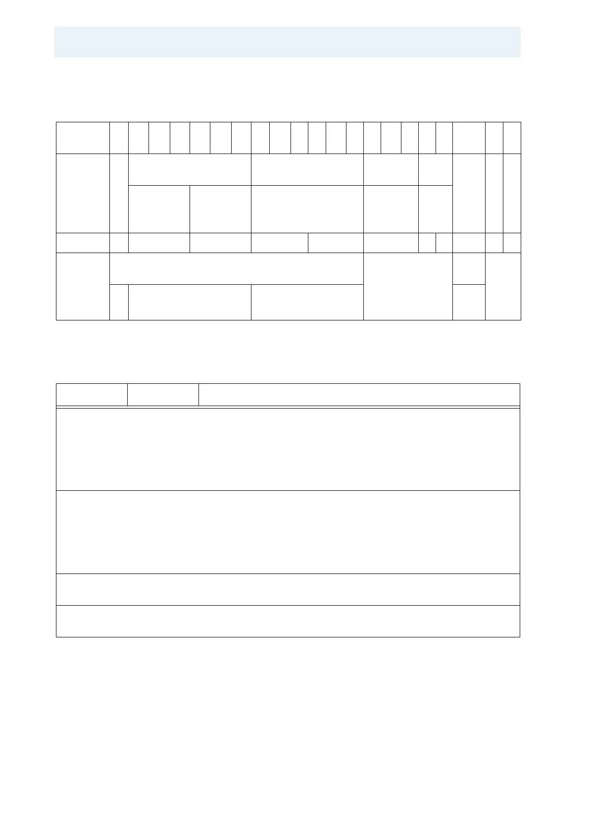
Table 5.1: Word on the LVDS 48 bit 80 MHz Parallel Interface
Bit 4
8
4
7
... 4
4
4
3
... 3
8
3
7
... 2
2
2
1
... 1
8
1
7
... 6 5 4 3 2 1
Field P
A
R
MSB Address MSB Data Data
(res)
(res) !LA
ST
!
V
A
L
I
D
!I
N
G
ADD<9..6> ADD<5..0> ADD<19..0> gnd gnd
Number 1 4 6 16 4 12 1 1 1 1 1
Con-
nected to
DSP
Data Bus
or Logic
DSP Data Bus Bit: not connected DSP
Bit
Logic
3
1
29..20 19..0 30
Table 5.2: Bit Fields of the DPP Input and Output Word
Field Value Description
!NG Next gradient bit; high active in FIFO; low active on the LVDS interface.
0 Leads only to the Next gradient, the word does not contain data,
!Valid=0 in the same 48 bit word was an error.
1 !Valid=0 and Out=1 means a gradient value is transferred without the
Next gradient.
!VALID Gradient data valid bit; high active in FIFO; low active on the LVDS
interface.
0 The word contains only data and no „Next Gradient“. !NG=0 in the
same word was an error.
1 There is no gradient data in this word.
PAR Parity bit, even parity, bit sum over the bits 1 to 47 (DPP only). The
DPP1 is software controlled.
!LAST 0 The last word in the gradient package is marked with !NG=0 or
!VALID=0; high active in FIFO; low active on the LVDS interface.