Installation and Connections
MATRIX CUBE - 7 -
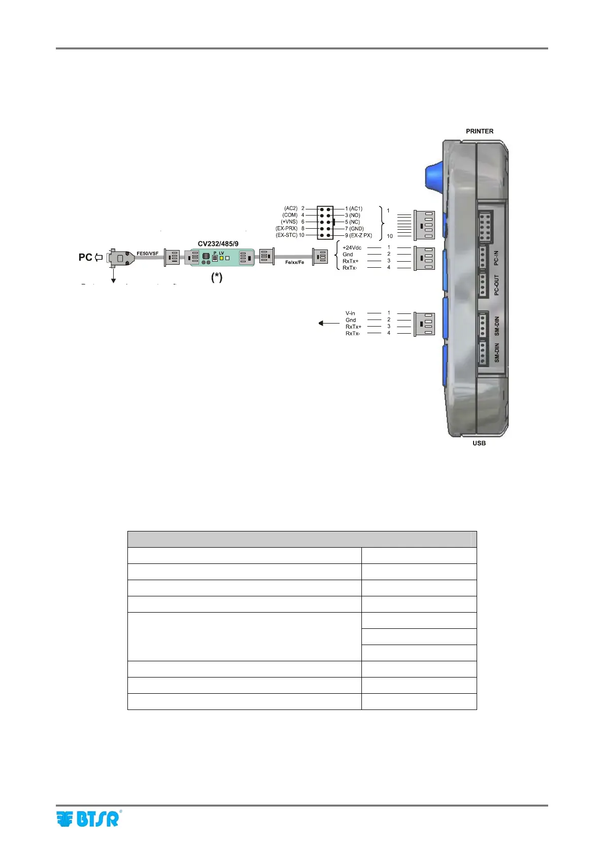
1.6 SMART MATRIX CUBE Interface
The following figure shows the electrical interface (pin assignment) of SMART MATRIX CUBE terminal.
The “Printer” and “USB” connectors are not currently used for MATRIX CUBE application.
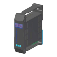
(*) Confirm that the LV green Led shows a double flashing (communication speed on
CV232/485/9 = 115 Kbps).
If necessary press the small P button.
SMART MATRIX CUBE Terminal Technical Characteristics
Power supply voltage 24 VDC ± 10%
Current absorption 100 mA Max
Protection fuse (SMART MATRIX) 1.5 A
Protection fuse (Sensor power supply) 1.5 A
0 – 24 VDC
VIL Max 1.2 VDC
Inputs
VIH Min 5 VDC
Operating temperature range +10° / +60° C
Storage temperature -25° / +85° C
Overall dimensions 140x80x31 mm
Supply voltage from SM-DIN/DUOLOOP
Software upgrading port
I/O interface
(currently not used)