20
Installation and wiring
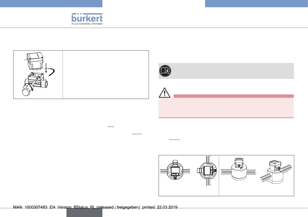
7.2.2. Assemble the SE32 with the S030
sensor-fitting
SE32
S030
1
2
3
→ Install the SE32 in the S030
sensor-fitting.
→ Turn the SE32 by a quarter turn.
→ Tighten the lateral screw(s) to lock
SE32 in place on the sensor-fitting.
(tightening torque max. 1 N·m,
i.e 0.74 lbf·ft).
Fig. 3 : Installation of the SE32 in the S030 sensor-fitting
7.2.3. Finalise the installation of the 8032
→ Wire the device and switch it on (see chap. 7.4).
→ Set the K-factor or determine it with Teach-In (see chap 9.5.2)
7.3. Fluid installation of the SE32 with
an S077 sensor-fitting
The SE32 is inserted into an S077 sensor-fitting mounted on the
pipe. The SE32 is assembled on the S077 sensor-fitting by a
quarter-turn rotation system:
1. Install the S077 sensor-fitting on the pipe,
2. Assemble the SE32 with the S077 sensor-fitting,
3. Finalise the installation.
7.3.1. Install the S077 sensor-fitting on the
pipe
→ Select an S077 sensor-fitting adapted to the viscosity of the
fluid in the pipe.
To select a sensor-fitting, refer to the technical data sheet
for the relevant sensor-fitting.
Caution
Risk of damage when installing the sensor-fitting.
▶ Follow the installation instructions given in the Operating
Instructions for the sensor-fitting.
→ Install the sensor-fitting S077 on the pipe in such a way that:
- the spindles of the oval gears are set horizontally, as shown in
Fig. 4.
- the installation instructions given in the Operating Instructions
of the sensor-fitting used are respected.
Correct Incorrect
Fig. 4 : The spindles of the oval gears must be horizontal
English
Type 8032 - SE32