24
Installation and wiring
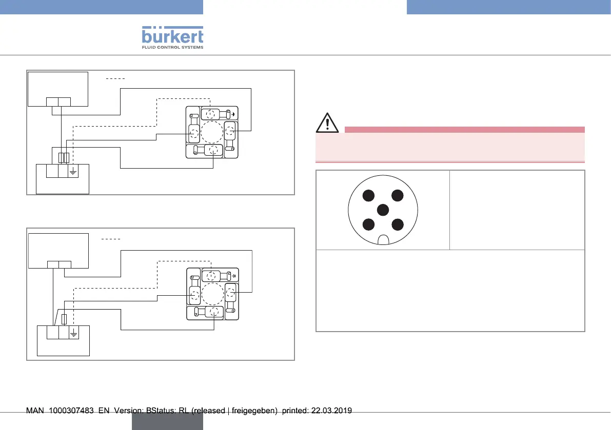
Power cable shield
Load
(solenoid valve,
for example)
Power supply
NPN transistor
output
12-36 V DC
+ -
+-
1
3
2
(*)
V+
0 V DC
Fig. 9 : NPN wiring of the transistor output of a version with
EN 175301-803 fixed connector
Power cable shield
Load
(solenoid valve,
for example)
Power supply
PNP transistor
output
+ -
1
3
2
(*)
V+
0 V DC
+-
Fig. 10 : PNP wiring of the transistor output of a version with
EN 175301-803 fixed connector
(*) Functional earth
7.4.4. Wiring a version with 2 transistor
outputs and a 5-pin M12 male fixed
connector
Danger
Risk of injury due to electrical voltage
▶ Always plug in and tighten the connectors correctly.
1 2
4 3
5
1. V+ (12...36 V DC)
2. NPN transistor output
3. 0 V DC
4. PNP transistor output
5. Functional earth
→ The position of the 5-pin M12 fixed connector is adjustable:
→ Unscrew the locknut.
→ Turn the fixed connector to the desired position, by 360° max. to
prevent the cables from twisting inside the housing.
→ Tighten the locknut using a spanner, while keeping the fixed con-
nector in the desired position.
Fig. 11 : Allocation of the pins on the 5-pin M12 male fixed
connector
English
Type 8032 - SE32