25
Installation and wiring
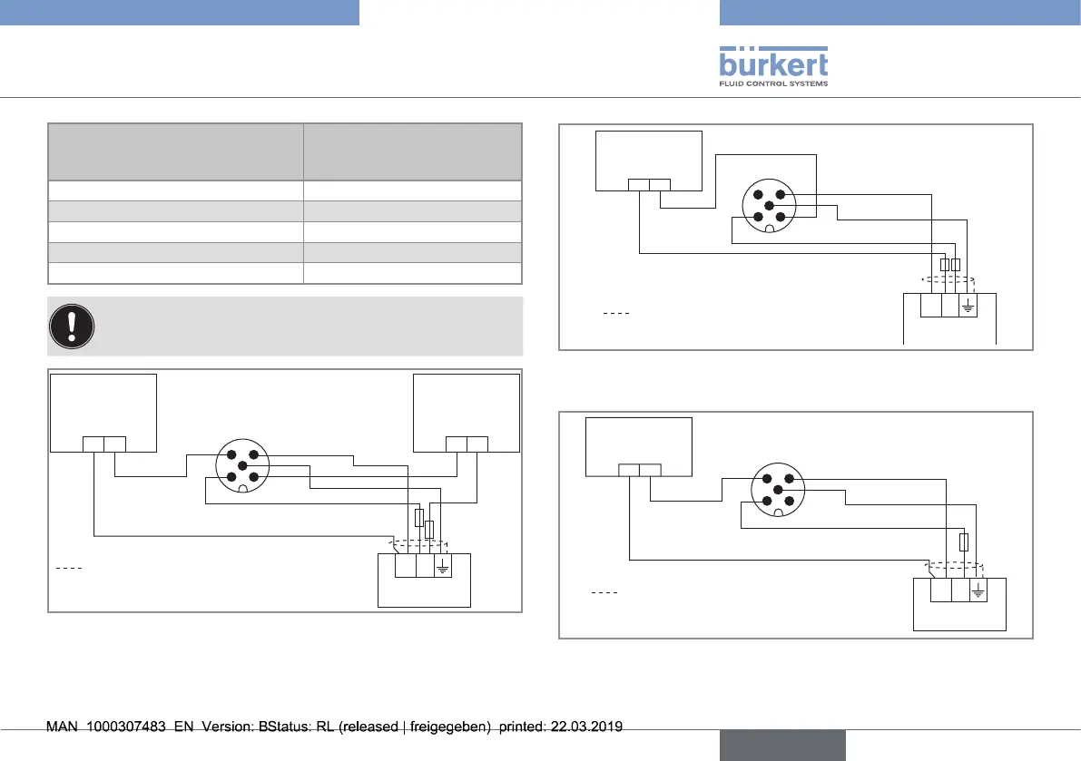
Pin of the M12 female cable
available as accessory equipment
(article number 438 680)
Colour of the wire (signal)
1 brown (12...36 V DC)
2 white (NPN transistor output)
3 blue (0 V DC)
4 black (PNP transistor output)
5 grey (functional earth)
When both transistor outputs are wired, they operate with
the same settings made within the OUT function.
12-36 V DC
+ -
+ -+ -
(*)
1 2
3 4
5
Load 1
(wired in PNP
mode)
Power supply
black
blue
brown
Power cable shield
grey
white
Load 2
(wired in NPN
mode)
Fig. 12 : Wiring both transistor outputs on a version with a 5-pin
M12 male fixed connector
+ -
1 2
3 4
5
+-
Load
(solenoid valve,
for example)
Power supply
white
blue
brown
Power cable shield
grey
Fig. 13 : Wiring of the NPN transistor output of a version with a
5-pin M12 male fixed connector
12-36 V DC
+ -
+-
(*)
1 2
3 4
5
Load
(solenoid valve,
for example)
Power supply
black
blue
brown
Power cable shield
grey
Fig. 14 : Wiring of the NPN transistor output of a version with a
5-pin M12 male fixed connector
(*) Functional earth
English
Type 8032 - SE32