30
Installation and wiring
The current output can be connected in either sourcing or
sinking mode.
See Fig. 26 and Fig. 27 for the related wiring charts.
7.4.8. Wiring the version with both relay
and current outputs (8-pin M12 fixed
connector)
Danger
Danger due to the operation of the relay outputs of a UL
device in a wet location.
▶ If a UL device is used in a wet location:
- energize the relay outputs with an alternating voltage of max.
16 Vrms and 22.6 Vpeak.
- or energize the relay outputs with a direct voltage of
max. 35 V DC.
Warning
Shock hazard due to the voltage at the relay terminals, which
is higher than 48 V.
▶ Before powering the device, always check that the connectors
are correctly plugged-in and tightened.
The device is not tight when the EN 175301-803 fixed
connector is not wired:
→ Unscrew the nut [1] (see Fig. 6) on the female con-
nector type 2508 supplied with the device.
→ Insert the plug with article number 444 509, supplied
with the device, into the cable gland.
→ Screw the nut back.
→ Plug the sealed type 2508 connector onto the
EN 175301-803 fixed connector.
1
2
3
1
2
3
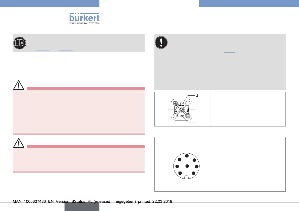
1. Common
2. Relay, normally closed (NC)
3. Relay, normally open (NO)
4. Not connected
Fig. 24 : Pin assignment on the EN 175301-803 fixed connector
4
3
1
2
8
5
6
7
1. V+ (12...36 V DC)
2. Not connected
3. 0 V DC
4. Positive 4...20 mA output
5. Not connected
6. Negative 4...20 mA output
7. Not connected
8. Functional earth
Fig. 25 : Allocation of the pins on the M12, 8-pin fixed connector
English
Type 8032 - SE32