31
Installation and wiring
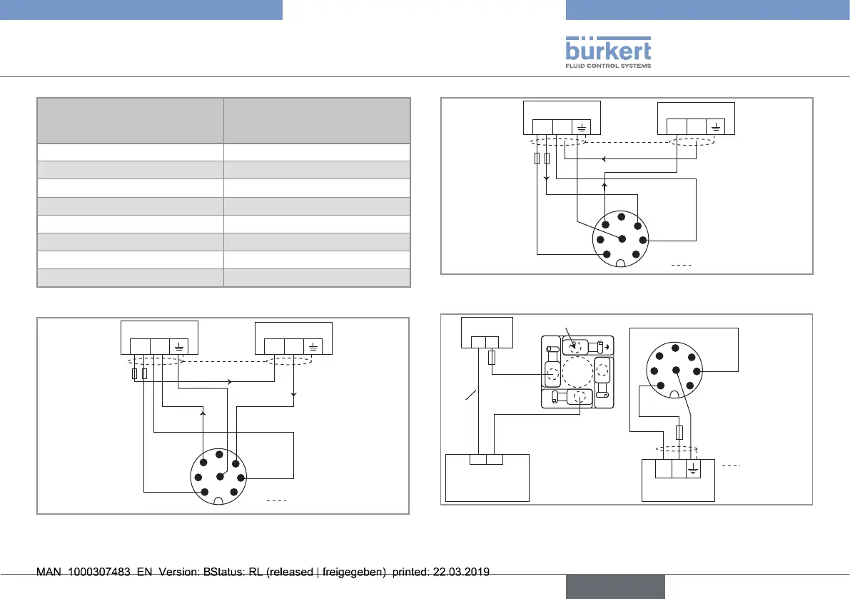
Pin of the 8-pin M12 female cable
available as an accessory equipment
(article number 444 800)
Colour of the wire (signal)
1 white (12...36 V DC)
2 not connected
3 green (0 V DC)
4 yellow (positive 4...20 mA output)
5 not connected
6 pink (negative 4...20 mA output)
7 not connected
8 grey (functional earth)
The current output can be connected in either sourcing or sinking mode.
+
-
(*)
+
-
12-36 V DC
4
3
1 2
5
6
7
8
i
i
i
Power supply
4...20 mA input
(at external
instrument)
white
green
yellowpink
shield
grey
Fig. 26 : Wiring of the current output, in sinking mode, of a version
with an 8-pin M12 fixed connector
+
-
i
+
-
4
3
5
6
7
8
12-36 V DC
(*)
i
i
shield
grey
Power supply
4...20 mA input
(at external
instrument)
white
green
yellow
pink
Fig. 27 : Wiring of the current output, in sourcing mode, of a
version with an 8-pin M12 fixed connector
12-36 V DC
+ -
1
3
2
(*)
L
250 V AC
N
(1)
4
3
1 2
5
6
7
8
Power cable
shield
grey
Power supply (2)
white
green
not connected
Load (solenoid
valve, for example)
Relay output, normally open
(NO)
Fig. 28 : NO wiring of the relay output of a version with an 8-pin
M12 fixed connector
English
Type 8032 - SE32