26
Installation and wiring
7.4.5. Wiring of the version with a single
relay output
Danger
Danger due to the operation of the relay outputs of a UL
device in a wet location.
▶ If a UL device is used in a wet location:
- energize the relay outputs with an alternating voltage of max.
16 Vrms and 22.6 Vpeak.
- or energize the relay outputs with a direct voltage of
max. 35 V DC.
Warning
Shock hazard due to the voltage at the relay terminals, which
is higher than 48 V.
▶ Before powering the device, always check that the connectors
are correctly plugged-in and tightened.
1
2
3
1
2
3
1. Common
2. Relay, normally closed (NC)
3. Relay, normally open (NO)
4. Not connected
Fig. 15 : Pin assignment on the EN 175301-803 fixed connector
The device is not tight when the EN 175301-803 fixed
connector is not wired:
→ Unscrew the nut [1] (see Fig. 6) on the female con-
nector type 2508 supplied with the device.
→ Insert the plug with article number 444 509, supplied
with the device, into the cable gland.
→ Screw the nut back.
→ Plug the sealed type 2508 connector onto the
EN 175301-803 fixed connector.
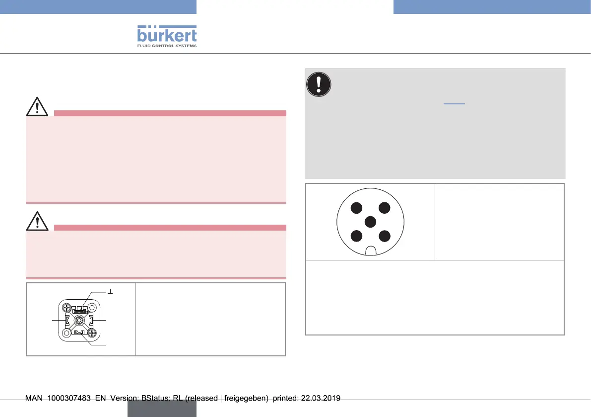
1 2
4 3
5
1. V+ (12...36 V DC)
2. not connected
3. 0 V DC
4. not connected
5. Functional earth
The position of the 5-pin M12 male fixed connector is adjustable:
→ Unscrew the locknut.
→ Turn the fixed connector to the desired position, by 360° max.
to prevent the cables from twisting inside the housing.
→ Tighten the locknut using a spanner, while keeping the fixed
connector in the desired position.
Fig. 16 : Pin assignment of the 5-pin M12 male fixed connector
English
Type 8032 - SE32