27
Installation and wiring
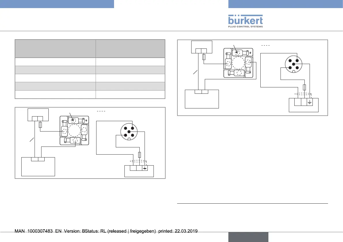
Pin of the M12 female cable
available as accessory equipment
(article number 438 680)
Colour of the wire (signal)
1 brown (V+)
2 not connected
3 blue (0 V DC)
4 not connected
5 grey (functional earth)
12-36 V DC
+ -
1 2
3 4
5
1
3
2
(*)
L
250 V AC
N
(1)
not connected
Load
(solenoid valve,
for example)
Power supply
Relay output, normally open
(NO)
Power cable shield
brown
grey
blue
Fig. 17 : NO wiring of the relay output of a version with one 5-pin
M12 and one EN 175301-803 fixed connectors
12-36 V DC
+-
1 2
3 4
5
1
3
2
L
N
(1)
Power cable shield
brown
grey
blue
not connected
Load
(solenoid valve,
for example)
Power supply
Relay output, normally
closed (NC)
Fig. 18 : NC wiring of the relay output of a version with one 5-pin
M12 and one EN 175301-803 fixed connectors
(1) Use a voltage limiter depending on the load selected, e.g. for the solenoid
valve, an EN 175301-803 fixed connector with integrated varistor.
(*) Functional earth
English
Type 8032 - SE32