21
Installation and wiring
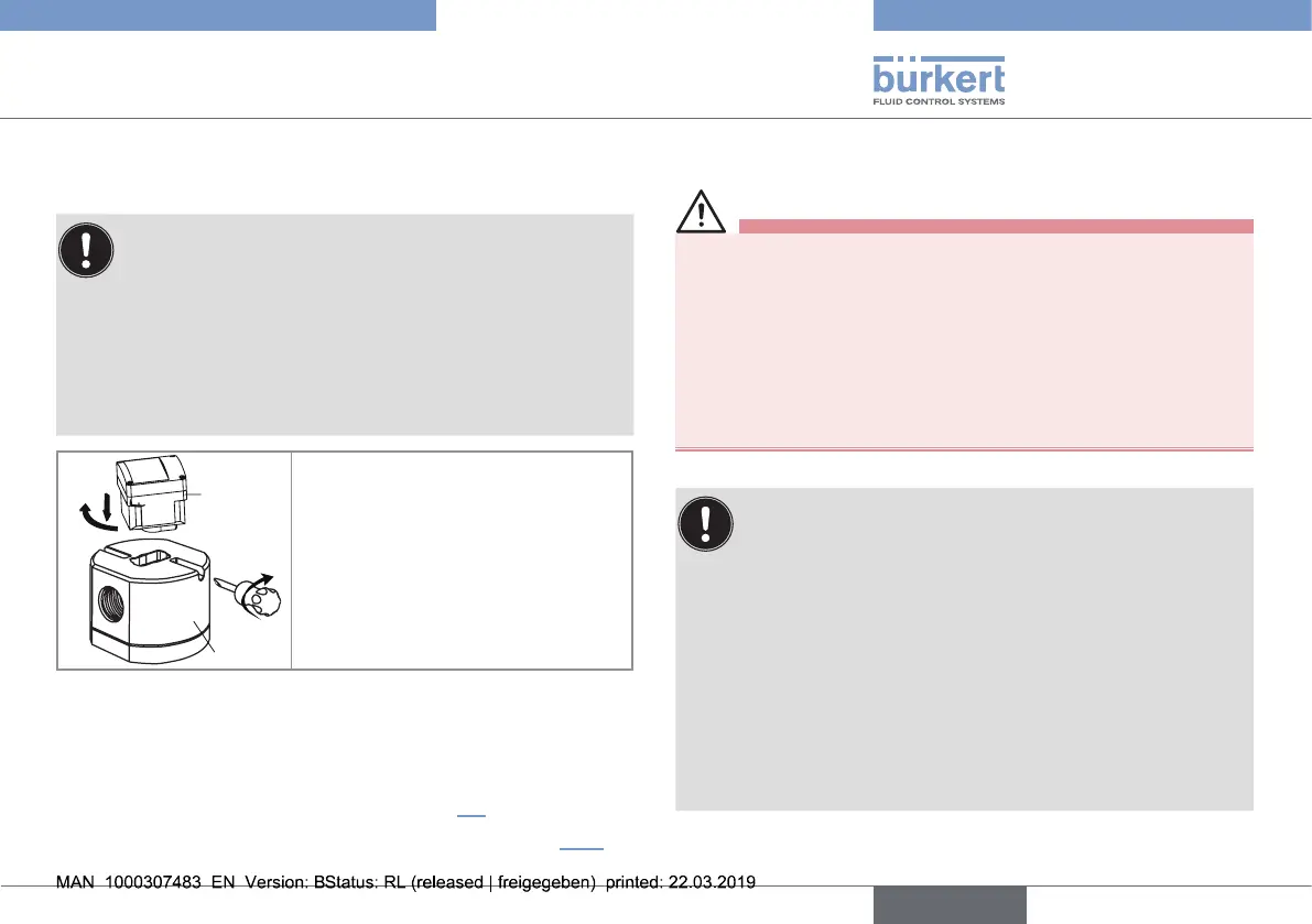
7.3.2. Assemble the SE32 with the S077
sensor-fitting
The SE32 only detects one rotation direction of the oval
gears of a S077 sensor-fitting.
• If the combination SE32 with sensor-fitting S077 does
not run properly, once assembled and energized, do the
following:
→ remove the SE32 from the S077 sensor-fitting,
→ turn the SE32 by 180°,
→ insert the SE32 back into the S077.
SE32
3
2
1
→ Insert the SE32 in the S077
sensor-fitting.
→ Turn the SE32 by a quarter turn.
→ Tighten the lateral screws to lock
the SE32 in place on the S077
sensor-fitting (tightening torque
max. 1 N·m, i.e 0.74 lbf·ft).
Fig. 5 : Installation of the SE32 in the S077 sensor-fitting
7.3.3. Finalise the installation of the SE32
with S077 sensor-fitting
→ Wire the device and switch it on (see chap. 7.4).
→ Set the K-factor or determine it with Teach-In (see chap 9.5.2)
7.4. Wiring
Danger
Risk of injury due to electrical voltage
▶ If a 12...36 V DC powered version is installed either in a wet
environment or outdoors, all the electrical voltages must be of
max. 35 V DC.
▶ Disconnect the electrical power for all the conductors and iso-
late it before carrying out work on the system.
▶ Observe all applicable accident protection and safety regula-
tions for electrical equipment.
• Use shielded cables with a temperature limit of 80°C
minimum.
• Use a high quality electrical power supply, filtered and
regulated.
• Protect the power supply by means of a 1 A fuse and a
switch.
• Protect the power supply of each transistor by means of a
125 mA fuse.
• Protect the relays by means of a max. 3 A fuse and a
circuit breaker (depending on the process).
• Do not apply both a dangerous voltage and a safety extra-
low voltage to the relays.
English
Type 8032 - SE32