23
Installation and wiring
6
5
→ Place the seal [5] between the connector and
the EN 175301-803 fixed connector on the
device and then plug the type 2508 connector
into the fixed connector.
→ Insert and then tighten the screw [6] to ensure
tightness and correct electrical contact.
Fig. 6 : Assembling the female connector type 2508 (supplied)
4 3 2 1
→ Unscrew the nut [1] on the body [4].
→ Insert the cable into the nut [1], the cable
clamp [2] and the seal [3], and then into
the body [4].
5,5
11,5
20
5
→ Strip 20 mm of the cable.
→ Cut the central wire (earth) so that its
length is equal to 11,5 mm.
→ Expose 5.5 mm of the wires on the
stripped cable.
→ Insert each wire into the appropriate pin
on the terminal block [5] (see chap. 7.4.4
to 7.4.8).
→ Screw the terminal block [5] once wired
to the body [4].
→ Tighten the connector nut [1].
Fig. 7 : Assembling an female M12 connector (not supplied)
7.4.3. Wiring a version with transistor
output and EN 175301-803 male
fixed connector
Danger
Risk of injury due to electrical voltage
▶ Always plug in and tighten the connectors correctly.
The device is not tight when the EN 175301-803 fixed
connector is not wired:
→ Unscrew the nut [1] (see Fig. 6) on the female con-
nector type 2508 supplied with the device.
→ Insert the plug with article number 444 509, supplied
with the device, into the cable gland.
→ Screw the nut again.
→ Plug the sealed type 2508 connector onto the
EN 175301-803 fixed connector.
1
2
3
1
2
3
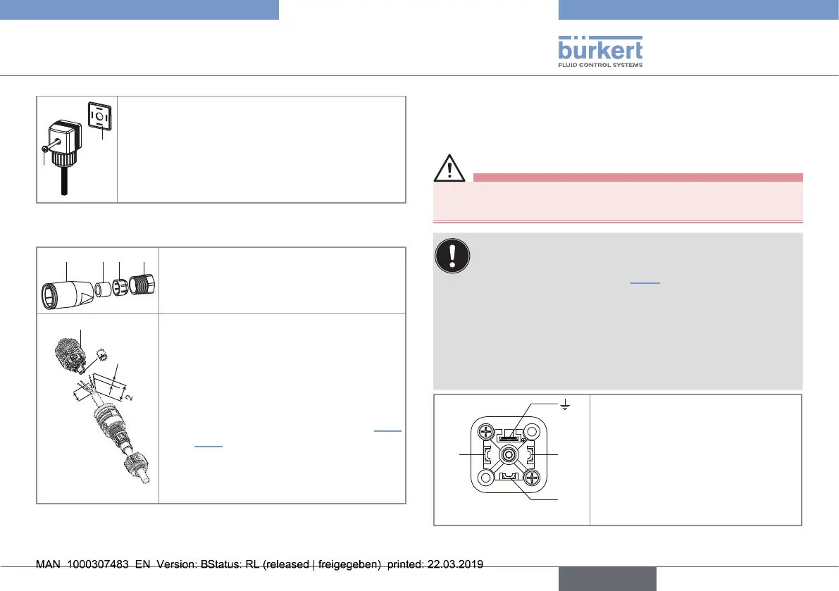
1. V+ (12...36 V DC)
2. Transistor output (NPN or PNP)
3. 0 V DC
4. Functional earth
Fig. 8 : Pin assignment of the EN 175301-803 fixed connector
English
Type 8032 - SE32