55
Operating and commissioning
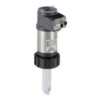
Type 8228
The accuracy of the conductivity measurements is influenced by:
• the drift of the zero point of conductivity. Correct the drift of the zero point with the function ZERO CALIB. To
be done if the conductivity of the air measured by the conductivity sensor is higher than 10 µS/cm (see "Cali-
brate the zero point of conductivity (function "Zero Calib." of the menu "Probe")", page 56).
• the conductivity cell constant:
- determine the cell constant of the sensor used with the function CALIBRATION (this calibration updates the
last calibration date in the “Last cal. date” function of the CALIB INTERVAL sub-menu hereafter). See "Cali-
brate the conductivity sensor (“Calibration” function in the “Probe” menu)", page 57,
- or enter the cell constant (marked on the calibration certificate of the device) in the function CELL CON-
STANT. The entering of the cell constant does not update the last calibration date in the “Last cal. date”
function of the CALIB INTERVAL sub-menu. The function CELL CONSTANT makes it also possible to read
the value of the constant which has been determined with the function CALIBRATION.
• the correction factor of the fitting. Enter the correction factor related to the fitting S020 used in the function
K-FITTING. The correction factor depends on the shape, the material and the diameter of the fitting used. The
following table gives the correction factors of the fittings S020.
Tab. 1: Correction factors of the fittings S020, depending on the shape, the material and the DN of the fittings
DN
Fittings with true union
connections or fittings with
weld ends
Fittings with internal or
external thread connections
or fittings with weld end
connections
Measurement
chamber Welding sockets or fusion
spigots
PVDF PP PVC Brass Stainless steel
Stainless
steel
PVDF PP
<32 1,08 1,08 1,08 0,99 0,99 - - - -
32 1,08 1,08 1,08 0,99 0,99 0,99 - - -
40 1,04 1,04 1,04 0,99 0,99 0,99 - - -
50 1,02 1,02 1,02 0,99 0,99 0,99 0,99 - -
65 - - - - - - 0,99 1,02 1,02
80 - - - - - - 0,99 1,02 1,02
100 - - - - - - 1,00 1,02 1,02
>100 - - - - - - 1,00 1,00 1,00
CELL CST TDS: enter the TDS factor suited to your process. The TDS factor allows for calculating the amount
of Total Dissolved Solids (TDS), in ppm, depending on the measured conductivity. The default TDS factor is 0,46
(NaCl)
CALIB INTERVAL: read the date of the last calibration (function “Last cal. date”) and set the periodicity of cali-
brations, in days (function “Interval”): the device generates a “maintenance” event by displaying the
icon and a
“warning” message, each time a calibration is due. Set function “Interval” to “0000 days” to ignore the function.
• The "warning" message may be associated with one or other or both transistor outputs (see
chap. 9.11.10).
• See also chap. "10.3 Solving a problem".
TEACH SPECIAL: define the temperature compensation curve specific to your process. The curve thus deter-
mined and memorised is used by the device when you choose “Special” in the “Comp.” function in the menu
“Param - Sensor” (see chap. 9.11.11). See also "Define the temperature compensation curve specific to your
process (“Teach special” function in the”Probe” menu)", page 59.
The compensation curve determined with the function TEACH SPECIAL cannot be transferred to another
device with the function DOWNLOAD (see chap. 9.11.1).
English